ETA Systems FC01-LQ User Manual
Page 16
monitoring head should be aligned
in direction of flow (see arrow)
14
L
14
ш1
8
ш22
SW20
Type
L
CSF-…L43…
190
CSF-…L30…
300
CSF-…L40…
400
M
16
x
0
.75
roun
d con
nector
fig. 6
Flow Meter FC01-LQ
Flow Meter FC01-LQ
10
Installation
10
Installation
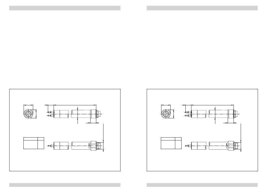
2.2.2 Monitoring head CSF-11 with adjustable immersion depth
Application:
pipelines with nominal pipe diameters > DN50
Medium:
liquids
Style:
smooth shank, 18 mm dia., immersion depth adjustable within
the PG16 cable gland (accessory) or mounting in the stainless steel
cutting ring gland
Material of the area exposed to medium:
-
M1 sensor and shank stainless steel 1.4571 /AISI 316 Ti (sensor)
-
M7 sensor stainless steel 1.4571 /AISI 316 Ti, shank aluminium
Accessories:
-
cable gland PG16 nickel-plated brass (see fig. 7)
-
threaded installation bush stainless steel 316 (cutting ring) (see fig. 7)
monitoring head should be aligned
in direction of flow (see arrow)
14
L
14
ш1
8
ш22
SW20
Type
L
CSF-…L43…
190
CSF-…L30…
300
CSF-…L40…
400
M
16
x
0
.75
roun
d con
nector
fig. 6