1 system linking, 2 set keyboard id, 3 system monitor setting – Elmo ESD-CC1 User Manual
Page 16
System Setting Mode:
4.3.1 System Linking
Menu 1.1 allow you to search for active cameras on the RS485 control bus again, press "◄" or "►" key to start
searching.
4.3.2 Set Keyboard ID
Menu 1.2 allow you to set up the ID number of this keyboard, use "◄" or "►" key to change the number. The default ID
is 000, if there are more than one keyboard in the same system, they must have different ID address to avoid
communication conflict.
4.3.3 System monitor setting
When you use the keyboard to control devices, it needs Monitor to see the image to prevent wrong actions. There are four
sources you can select, the first one is Multiplexer’s main monitor output, the second one is Matrix’s output, the third one
is the SuperMPX mode, and the last one is SuperMMX mode.
When you select Item a.(as Fig.4.3.3.1), the image of camera will be displayed on Multiplexer’s main monitor. On the
other hand, when select Item b. (as Fig.4.3.3.2 and hit “ENTER”), please input the Output Channel/Monitor no. (as
Fig.4.3.3.5) and hit “ENTER” key. The image of camera will be displayed on Matrix’s monitor. Hit “ESC” to go back
System mode.
Please refer Appendix C to see the architecture of SuperMPX and SuperMMX.
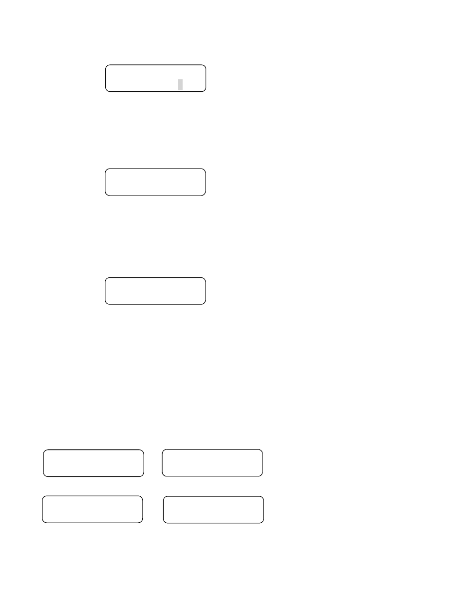
1.0 System Setting
Enter password [____]
Fig.4.3
1.1 System Linking
Press ◄► to search..
Fig.4.3.1
1.2 Set Keyboard ID
(0 or 240-254):000
Fig.4.3.2
1.3 System Monitor
a.MPX main monitor
Fig.4.3.3.1
1.3 System Monitor
b.Matrix output
Fig.4.3.3.2
1.3 System Monitor
c.SuperMPX mode
Fig.4.3.3.3
1.3 System Monitor
d.SuperMMX mode
Fig.4.3.3.4
16