4 voltage adjustment, Voltage adjustment, Terminal locations of the rcw 350w power supply – KEPCO RCW 350W Series User Manual
Page 10
8
RCW350W 120607
3.4 VOLTAGE ADJUSTMENT
The unit is provided with a voltage adjustment control (Vadj) (see Mechanical Outline Drawing, Fig-
ure 3). To adjust voltage, first place the unit under an operating load, then monitor the (+) S and (–)
S Sense terminals with a precision voltmeter and turn the voltage control to the desired operating
value. Refer to Table 1 for the recommended Adjustment Range of all the RCW 350W Models (see
Figure 6).
NOTE: Actual output voltage can exceed recommended range values.
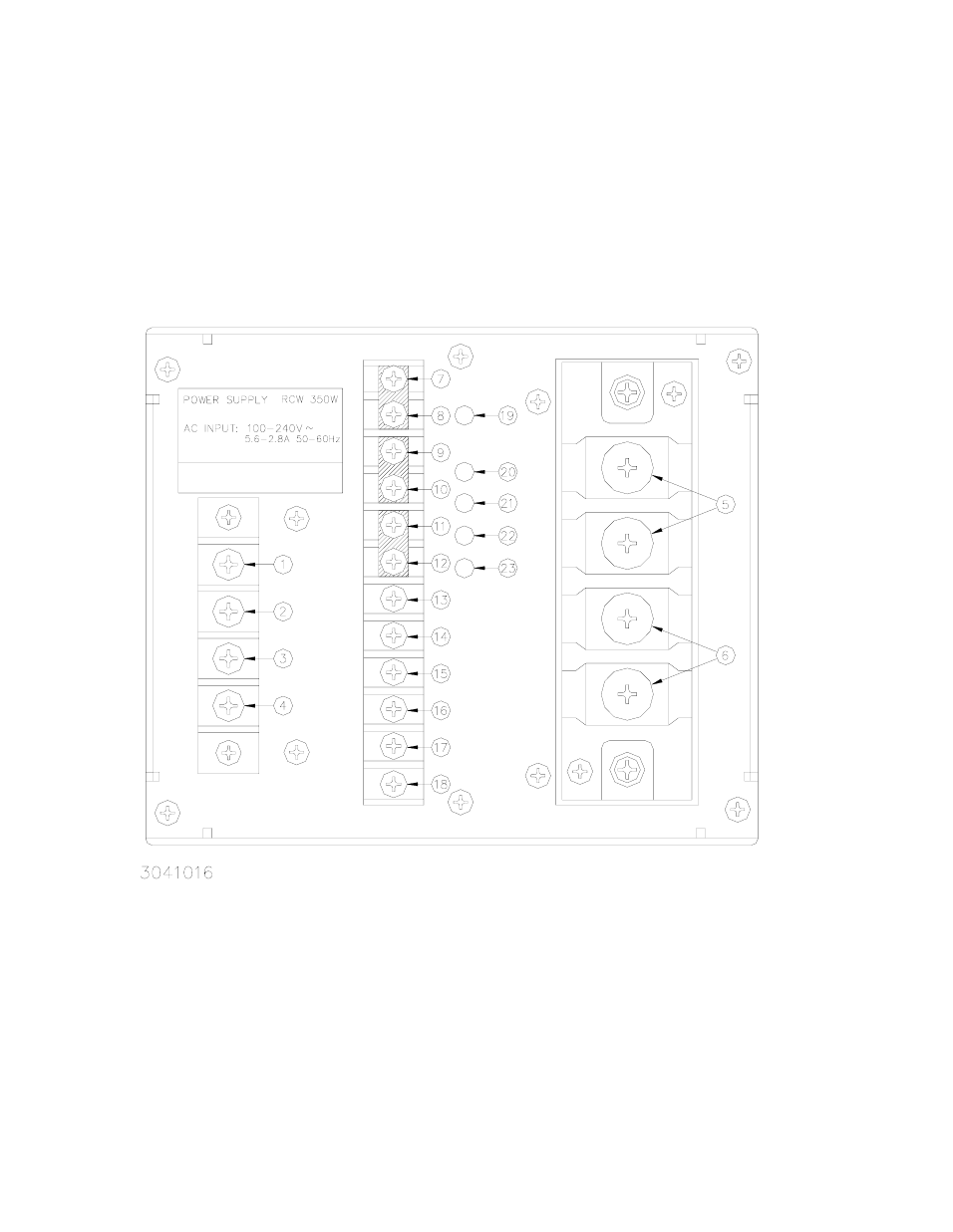
FIGURE 6 TERMINAL LOCATIONS OF THE RCW 350W POWER SUPPLY
LEGEND:
1.
Ground
2.
No Connection
3.
AC Input (Line)
4.
AC Input Neutral
5.
DC Output (+)
6.
DC Output (-)
7.
(+) S Remote Sense
8.
(+) M (Output Voltage Monitor
9.
(–) M (Output Voltage Monitor)
10. (–) S Remote Sense
11. REF Reference Voltage
12. RV (Output voltage variable)
13. CB (Current Balance)
14. (+) RC (Remote ON-OFF)
15. (–) RC (Remote ON-OFF)
16. (+) AL Alarm OV, UV, Thermal, Fan)
17. (+) PF Alarm Input Power Fail)
18. (–) AL, (–) PF (Alarm common)
19. ON Output Voltage ON
20.
ADJ (Output Voltage Adjustment)
21. OV (Output overvoltage LED, red)
22. UV (Output undervoltage LED, red)
23. FAN (Fan alarm LED red)
(+) S/(+) M, (–) S/(–) M, and REF/RV are
connnected by shorting links