Direct or non-direct venting, Venting instructions: downflow – Thermo Pride Thermo Pace Downflow/Horizontal Furnace (CSA) User Manual
Page 8
Page 8
Installer’s Information Manual
6. Follow the lighting instructions. Place the appliance
being inspected in operation. Adjust thermostat so
appliance shall operate continuously;
7. Test for drafthood equipped appliance spillage at the
drafthood relief opening after 5 minutes of main burner
operation. Use the flame of a match or candle;
8. After it has been determined that each appliance
connected to the venting system properly vents when
tested as outlined above, retu rn doors, windows,
exhaust fans, fireplace dampers and any other gas -
burning appliance to th eir previous conditions of use;
9. If improper venting is observed during any of the above
tests, the venting system must be corrected. Follow
the National Fuel Gas Code, ANSI Z223.1/NFPA 54 or
CAN/CGA B149 Installation Codes to correct improper
vent operation. Any "common vent" re-sizing must
approach minimum size determined using current
venting tables.
DIRECT OR NON-DIRECT VENTING?
This furnace may be installed using either direct venting or
non-direct venting.
A direct-vented furnace takes all air for combustion directly
into the furnace through a pipe from outdoors. To direct
vent this furnace you must install two pipes to the outdoors.
One pipe supplies combustion air that the fu rnace needs to
operate. The other pipe vents flue gases to the outdoors.
Use direct venting when indoor air may be contaminated
with chemicals such as chlorine, fluorine, bromine or iodine.
When these chemicals are burned with natural gas or
propane gas, acids are produced which may decrease heat
exchanger life. You should also consider direct venting
when furnace is installed in a space with limited combustion
and ventilation air. See “CONFINED SPACE
INSTALLATION” under the “NON-DIRECT VENTING”
instructions.
A non-direct vented furnace takes all air for combustion
from the room in which fu rnace is installed. Non-direct
venting requires only one pipe for venting the flue gases to
the outdoors but you must make sure there is enough air for
combustion and ventilation.
VENTING INSTRUCTIONS: DOWNFLOW
1. Select venting option from Figure 9 that fits your
installation. Downflow furnaces can be vented through
top or either side. For direct venting, combustion air
can come through top or either side.
2. From parts package find the following parts: section of
2” PVC pipe, 2” PVC elbow, PVC flue outlet fitting, and
1/2” street ell.
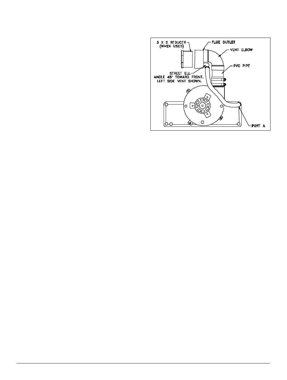
3. Cement 2” PVC pipe, 2” PVC elbow, and flue outlet
together as shown in Figure 8. Position flue outlet
such that street ell will be directly below vent elbow.
Figure 8. Downflow Vent Connection.
4. Cement 1/2” street ell to flue-outlet drain. Position
street ell so that it will be angled down and toward front
of furnace at a 45° angle when assembly is installed in
furnace.
5. Install large hose clamp over rubber coupling on
furnace draft inducer. Do not tighten hose clamp.
6. Push vent assembly into rubber coupling until it
bottoms out and tighten hose clamp securely.
7. From parts package find long condensate hose and
two hose clamps.
8. Attach condensate hose and one hose clamp to
inducer-pan port A, located in upper right-hand corner
of inducer pan. Hose should be curved toward 1/2”
street ell in flue outlet.
9. Attach other end of hose and remaining hose clamp to
1/2” street ell.
10. Some models are shipped with a 3-inch to 2-inch
reducer bushing. When venting with 2-inch pipe, install
reducer bushing in flue outlet fitting. See Table 1 or
Table 2 for correct vent diameter for your application.
11. Complete installation of venting system with field
supplied parts.
12. Support vent pipe at furnace. Do not allow draft
inducer and rubber coupling to support the weight of
the vent pipe.