Checking gas supply pressure, Pilot flame adjustment – Thermo Pride Thermo Pace Downflow/Horizontal Furnace (CSA) User Manual
Page 25
Installer’s Information Manual
Page 25
SECTION 12. GAS SUPPLY
PRESSURE AND PILOT
ADJUSTMENT
You will need a 0 to 15 inch water manometer with 0.1 inch
resolution and a 1/8" NPT manual shut-off valve to measure
actual gas pressure.
CHECKING GAS SUPPLY PRESSURE
1. Turn off gas at equipment shut-off valve in gas supply
line just ahead of fu rnace.
2. Remove three screws holding burner access panel in
place. Remove burner access panel.
3. Remove inlet pressure plug from gas control. See
Figure 24.
4. Install 1/8" NPT manual shut-off valve in hole vacated
by plug. Make sure valve is in off position.
5. Attach manometer to 1/8" NPT manual shut-off valve
just installed.
6. Slowly open equipment shut-off valve in gas supply line
just ahead of fu rnace.
7. Slowly open 1/8" NPT manual shut-off valve leading to
manometer.
8. Turn on all gas appliances attached to gas supply line.
9. With furnace operating, read gas supply pressure on
manometer.
??
Natural gas supply pressure must be between 5
and 7 inches W.C.
??
Propane gas (LP) supply pressure must be
between 11 and 13 inches W.C.
10. If gas supply pressure is not within these limits, call gas
supplier. Tu rn off all gas appliances attached to gas
supply line.
11. Shut off furnace.
12. Turn off gas at equipment shut-off valve in gas supply
line just ahead of furnace. Remove shut-off valve from
gas -control inlet pressure tap. Install pressure tap
plug. Turn on gas.
13. Replace burner access panel using three screws
removed in step 2.
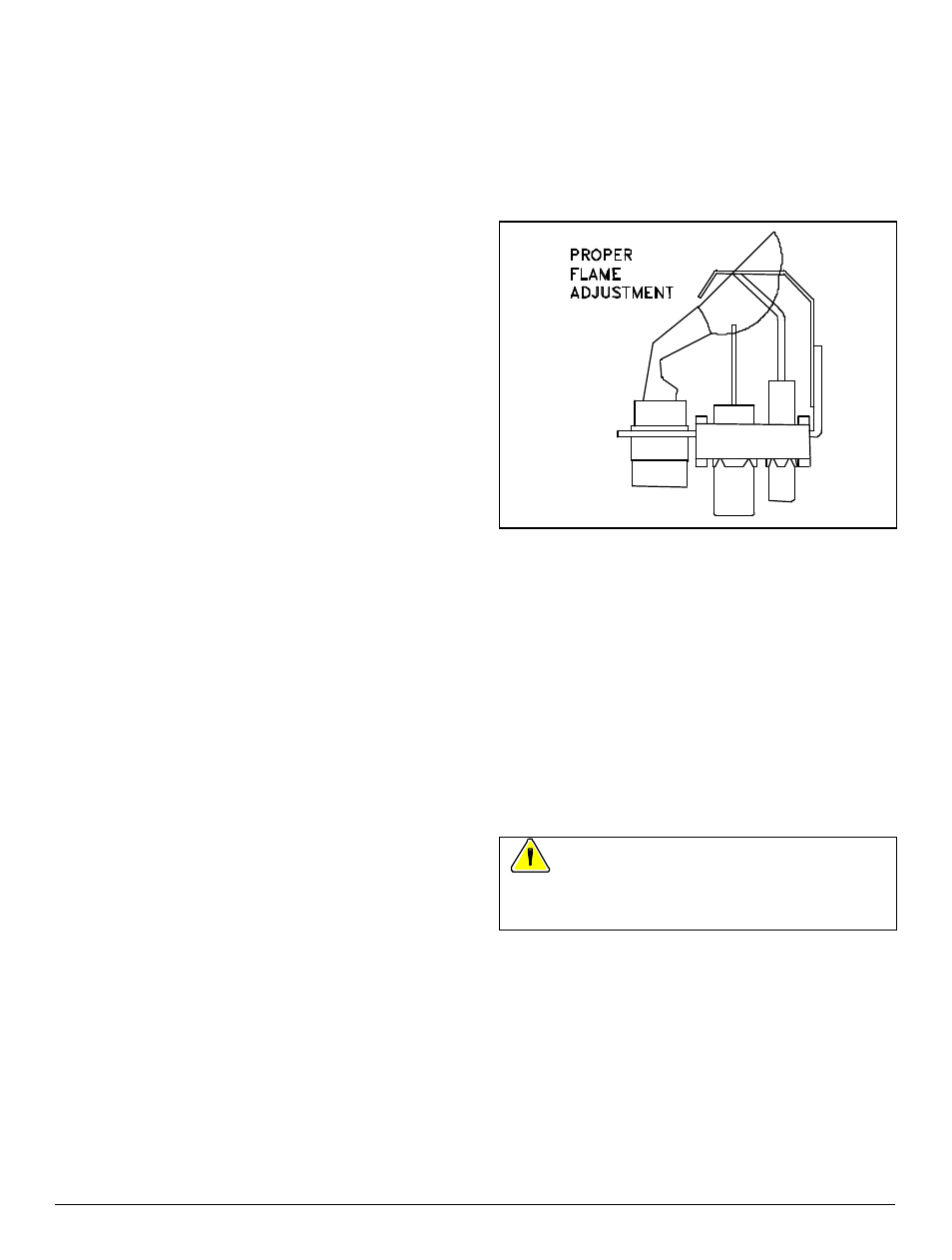
PILOT FLAME ADJUSTMENT
Before adjusting pilot flame, confirm that gas supply
pressure is correct, as explained above.
NOTE: Pilot flame adjustment was checked at the factory
and should not require adjustment. However; pilot
adjustment is possible if necessary.
1. Remove three screws holding burner access panel in
place. Remove burner access panel.
2. Start furnace following "Operating Instructions" on front
door.
3. Pilot flame should cover 1/2 inch of tip of flame sensor
as shown in Figure 29.
4. If you need to adjust pilot flame, remove pilot-
adjustment cover screw on gas control. Save cover
screw for re-installation. Tu rn inner adjustment screw
clockwise to decrease pilot flame; counter-clockwise to
increase pilot flame. Install cover screw and tighten to
torque of 5 inch-pounds to prevent gas leakage.
Figure 29. Pilot Flame Adjustment.
5. Check pilot-adjustment cover screw and gas -control
inlet-pressure-tap plug for gas leaks. Use a
commercial soap solution made for leak detection.
6. Replace burner access panel using three screws
removed in step 1.
SECTION 13. MANIFOLD
PRESSURE ADJUSTMENT
You will need a 0 to 15 inch water manometer with 0.1 inch
resolution and a 1/8" NPT manual shut-off valve to measure
actual manifold pressure.
WARNING: Correct manifold pressure is
necessary for proper ignition and b urner operation. Failure
to accurately adjust pressure could cause heat exchanger
failure.
Check gas -supply pressure first. Follow instructions in
Section 12, "Gas Supply Pressure and Pilot Adjustment."
1. Turn off gas at equipment shut-off valve in gas supply
line just ahead of fu rnace.
2. Remove three screws holding burner access panel in
place. Remove burner access panel.
3. Remove plug from manifold pressure tap in gas
control. See Figure 24.
4. Install 1/8" NPT manual shut-off valve in hole vacated
by plug. Make sure shut-off valve is in off position.