Drain trap instructions-- downflow position – Thermo Pride Thermo Pace Downflow/Horizontal Furnace (CSA) User Manual
Page 18
Page 18
Installer’s Information Manual
DRAIN TRAP INSTRUCTIONS--
DOWNFLOW POSITION
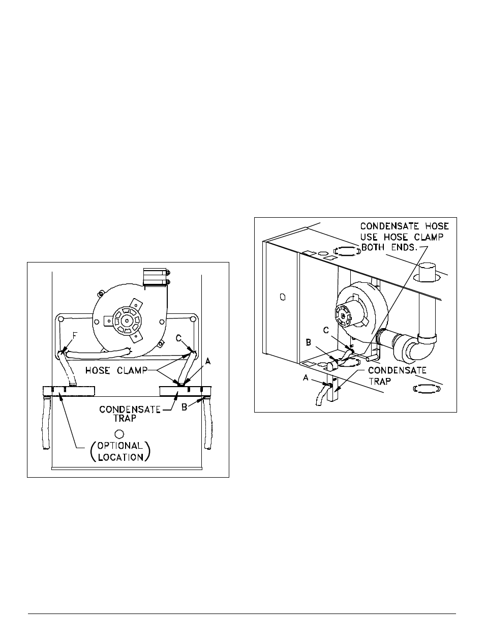
1. Select drain location option from Figure 21 that best fits
your installation. In downflow position, condensate trap
can be mounted for draining through either side of
furnace.
2. From parts package find the following parts:
condensate drain trap, 8 1/2” section of 13/16” OD
drain hose, and two small hose clamps.
3. From inside of casing, insert drain trap through hole in
side of casing, port B end first. Slide trap down with
casing between first set of guides. Trap will protrude
from casing about 1 inch with port B pointed down.
Port A of trap will be inside of casing and pointed up.
4. Attach condensate hose and one hose clamp to port A
of drain trap. Attach other end of condensate hose and
hose clamp to inducer-pan drain port. For right-side
drain, use inducer-pan port C, located in lower right-
hand corner of inducer pan. For left-side drain, move
rubber cap from inducer-pan port F, (located in lower
left-hand corner) to port C. Attach condensate hose to
port F.
Figure 21. Downflow Drain-Trap Installation.
5. Complete installation of condensate drain system from
condensate trap (port B) with field supplied parts.
DRAIN TRAP INSTRUCTIONS--
HORIZONTAL AIR-LEFT POSITION
1. See Figure 22 for drain trap location for your
installation. In horizontal positions, condensate drain
trap must be mounted through bottom side of furnace.
2. From parts package find the following parts:
condensate drain trap, 8 1/2” section of 13/16” OD
drain hose, and two small hose clamps.
3. From underside of casing, insert drain trap through
hole in casing, port B end first. Slide trap toward
inducer pan with casing between trap mounting guides.
Use first set of guides for 17 1/2” and 23 1/2” wide
models. Use second set of guides for 20 1/2” wide
models. Trap will protrude into casing with port B
pointed toward inducer-pan-drain port C. Port A of trap
will be outside of casing and pointed toward front of
furnace.
4. Cut condensate hose to a length of 4 1/2 inches.
Attach hose and one hose clamp to port B of drain trap.
Attach other end of condensate hose and hose clamp
to inducer pan drain port C.
5. Complete installation of condensate drain system from
condensate trap (port A) with field supplied parts.
Figure 22. Horizontal Air-Left Drain-Trap Installation.
DRAIN TRAP INSTRUCTIONS--
HORIZONTAL AIR-RIGHT POSITION
1. See Figure 23 for drain trap location for your
installation. In horizontal positions, condensate drain
trap must be mounted through bottom side of furnace.
2. From parts package find the following parts:
condensate drain trap, 8 1/2” section of 13/16” OD
drain hose, and two small hose clamps.