Thermo Pride Thermo Pace Downflow/Horizontal Furnace (CSA) User Manual
Page 28
Page 28
Installer’s Information Manual
Table 8. Propane (LP) Gas Orifice Size. (Millimeters)
ELEVATION
GAS
Up
2001
3001
4001
5001
6001*
7001*
8001*
9001*
HEATING*
to
to
to
to
to
to
to
to
to
VALUE
2000
3000
4000
5000
6000
7000
8000
9000
10000
(Btu/cu. ft.)
Feet
Feet
Feet
Feet
Feet
Feet
Feet
Feet
Feet
2500-2550
1.20
1.15
1.15
1.15
1.15
1.10
1.10
1.10
1.05
* Above 6000 feet, a high-altitude gas conversion kit must be used.
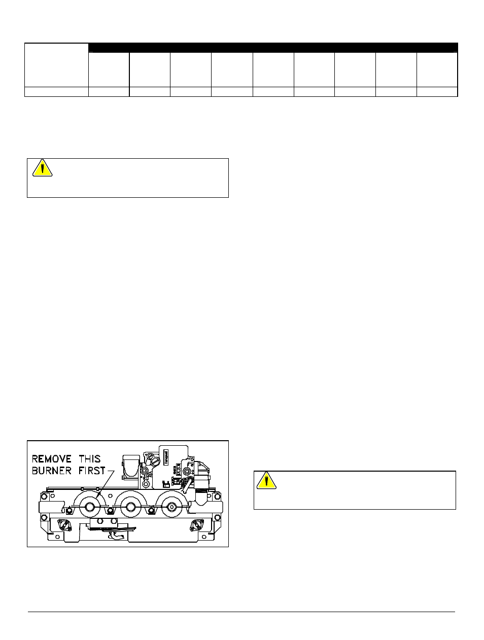
SECTION 17. CHANGING MAIN
BURNER ORIFICES
WARNING: To prevent electrical shock and gas
leaks, turn off electrical power and gas before changing
orifices.
Follow this procedure:
1. Turn off electricity at electrical disconnect switch next
to furnace.
2. Turn off equipment shut-off valve in gas supply line just
ahead of furnace.
3. Remove three screws holding burner access panel in
place. Remove burner access panel.
4. Starting with burner farthest from gas control, remove
main burner screws and main burners. Note how
burners overlap. Burner farthest from gas control is on
top. See Figure 31.
5. Remove original main burner orifices from manifold
pipe.
6. Carefully, hand thread new orifices into manifold pipe.
Do not cross-thread. Tighten to torque of 50 inch-
pounds.
7. Starting with burner closest to gas control, replace
main burners and main burner screws. Burner
mounting flange of burner farther from gas control
overlaps burner-mounting flange of burner closest to
gas control.
Figure 31. Main Burner Rem oval.
8. Check burner carry-over alignment. Burner carry-
overs may touch but not overlap adjacent burner carry-
overs. Replace screws.
9. Replace burner access panel using three screws
removed in step 3.
10. Open equipment shut-off valve in gas supply line just
ahead of furnace.
11. Set room thermostat to highest setting and to heating
mode.
12. Turn on electricity at electrical disconnect switch
located next to furnace. Furnace will light.
13. Visually check that each burner lights promptly.
14. Check gas input following Section 14, "Checking Gas
Input Rate."
15. Reset room thermostat to desired setting.
SECTION 18. ADJUSTING
BLOWER SPEED
Determine initial heating and cooling speeds in system
design stage. See Specification Sheet for airflow data.
Depending on tests performed in following secti ons, you
may need to change blower motor speed.
CAUTION: Heating speed tap should not be reduced below
factory setting. Doing so may result in inadequate air
circulation, and could cause excessive air temperature rise
through furnace. This could cause a high-temperature limit
switch to cycle burners on and off, reducing fu rnace
efficiency and shortening heat exchanger life.
All models have these four motor speed designations:
High Speed (HI)
Black wire
Medium High Speed (MH)
Blue wire
Medium Low Speed (ML)
Yellow wire
Low Speed (LO)
Red wire
WARNING: To prevent electric shock, turn off
electrical power to furnace before changing blower motor
speed.
1. To change cooling speed, move desired motor lead to
terminal marked 'COOL' on Fan Timer. See Figure 32.
Initial factory setting for cooling is high speed (black
wire).
2. To change heating speed, move desired motor lead to
terminal marked 'HEAT' on Fan Timer. See Figure 32.
Factory setting for heating is liste d in Table 9. Heating
speed should not be reduced below factory setting.