Venting instructions: horizontal air-left, Venting instructions: horizontal air-right – Thermo Pride Thermo Pace Downflow/Horizontal Furnace (CSA) User Manual
Page 10
Page 10
Installer’s Information Manual
VENTING INSTRUCTIONS: HORIZONTAL
AIR-LEFT
1. Select venting option from Figure 9 that fits your
installation. Horizontal furnaces can be vented through
top or through blower end of furnace (in most
applications). For direct venting, combustion air can
come through top or bottom.
2. From parts package, get PVC flue outlet fitting and
large hose clamp.
3. Install large hose clamp over rubber coupling on
furnace draft inducer. Do not tighten hose clamp. See
Figure 10.
4. Push flue outlet fitting into rubber coupling until it
bottoms out. Rotate flue outlet fitting until drain is on
bottom as shown in Figure 10. Tighten hose clamp
securely.
5. From parts package, get long condensate hose and
two hose clamps.
6. Long condensate hose must be cut to fit between flue
outlet drain and street ell. Proper length is 6¼ inches
for 17½ or 20½ inch wide furnaces and 8½ inches for
23½ inch wide furnaces.
7. Attach condensate hose and one hose clamp to flue
outlet fitting.
8. From parts package, get 1/2” street ell. Attach hose
and remaining hose clamp to 1/2” street ell. Test fit
street ell and hose assembly to inducer-pan port A,
located in lower right-hand corner of inducer pan. Note
the angle of the street ell.
9. Solvent weld street ell to inducer-pan port A at angle
noted in previous step.
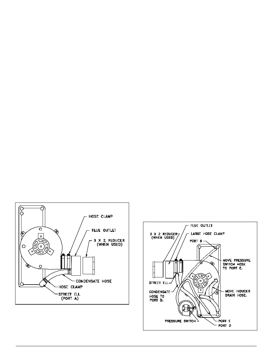
Figure 10. Horizontal Air-Left Vent Connection.
10. Some models are shipped with a 3-inch to 2-inch
reducer bushing. When venting with 2 -inch pipe, install
reducer bushing in flue outlet. See Table 1 or Table 2
for correct vent diameter for your application.
11. Complete installation of venting system with field
supplied parts.
12. Support vent pipe at furnace. Do not allow draft
inducer and rubber coupling to support the weight of
the vent pipe.
VENTING INSTRUCTIONS: HORIZONTAL
AIR-RIGHT
1. Select venting option from Figure 9 that fits your
installation. Horizontal furnaces can be vented through
top or through blower end of furnace (in most
applications). For direct venting, combustion air can
come through top or bottom.
2. Move inducer drain hose from middle drain port of
inducer to inducer drain port at bottom of inducer--
located near pressure switch. To do this, remove cap
from inducer drain port near pressure switch. Save
cap. Move hose from middle inducer drain hole to
uncapped port. Install cap on open port.
3. Move pressure switch hose from inducer pan port “B”
to inducer-pan port E. To do this, remove cap from
inducer-pan pressure port E, at pressure switch end of
inducer pan. Save cap. Move hose from inducer-pan
pressure port B to port E. Install cap on port B.
4. From parts package, get PVC flue outlet and 1/2” street
ell.
5. Cement 1/2” street ell to flue-outlet drain. Position
street ell so that it will be angled down and toward front
of furnace at a 45° angle when assembly is installed in
furnace.
6. Install large hose clamp over rubber coupling on
furnace draft inducer. Do not tighten hose clamp.
7. Push flue outlet into rubber coupling until it bottoms
out. Rotate flue outlet until street ell is on bottom as
shown in Figure 11. Tighten hose clamp securely.
Figure 11. Horizontal Air-Right Vent Connection.