Configuring a single video output, Composite enable, Fixed mode examples – Rosen Aviation 0700-006 : Video Distribution Amplifier User Manual
Page 7
Rosen Aviation
4. CONFIGURING A SINGLE VIDEO OUTPUT
Configuring a single video output depends on several variables.
z
Type and number of video inputs
z
Use of a source select switch (such as a controller, IR remote, or from the monitor)
z
Choice of inputs: composite source A, B, C, or D, and RGB source A or B
4.1. Composite Enable
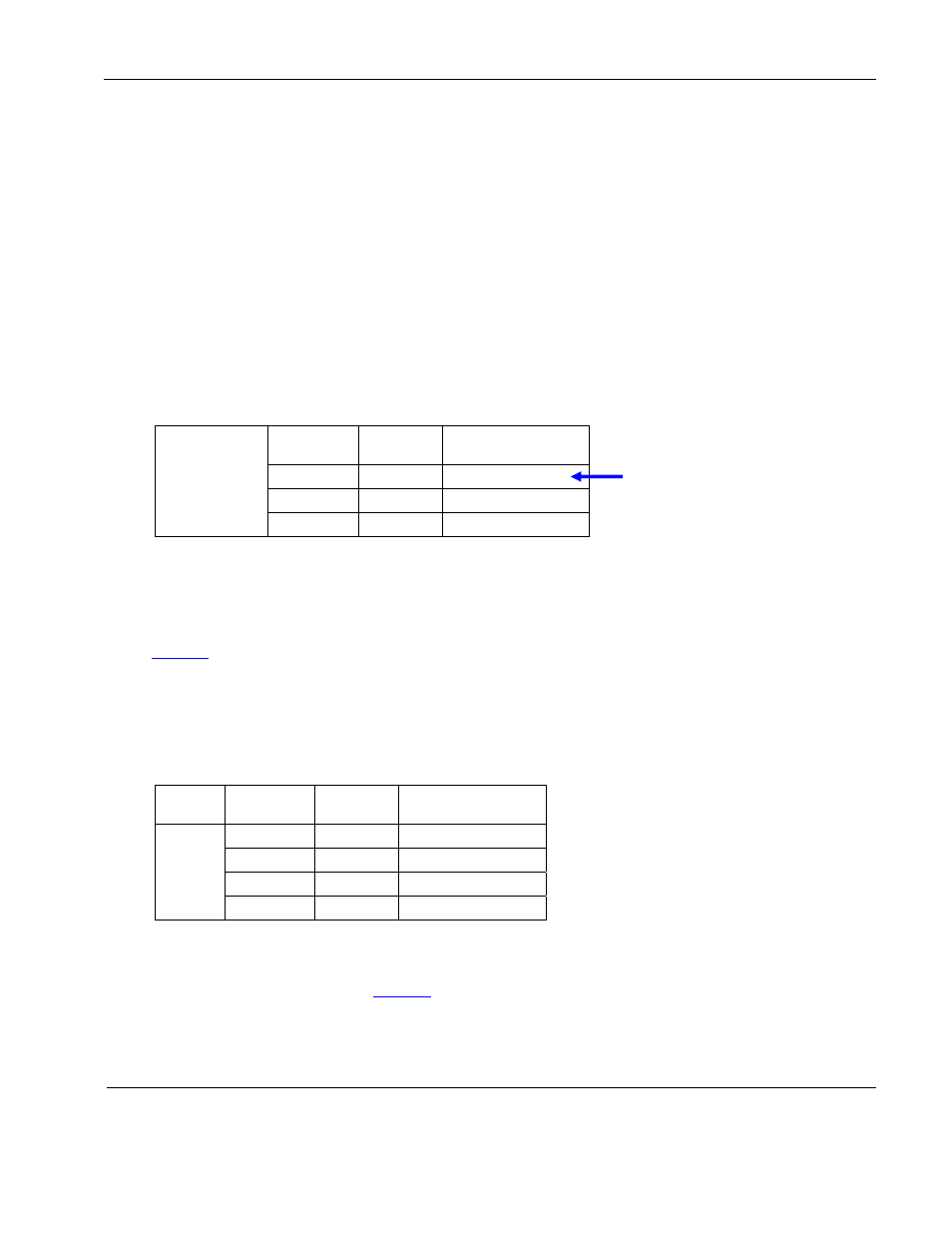
To enable video source C and/or D, you must set the Composite Enable switches SW7 and
SW8 in the middle bank, as shown in Table 1. For a switched mode configuration, leave the
Comp Output 1-8 switches OFF.
Table 1 Composite Enable DIP switches in the middle bank
Composite
Enable
Mid DIP
SW7
Mid DIP
SW8
Composite
Source
OFF
OFF
A & B only
N/A*
ON
A, B, C, & D
ON
OFF
A, B, & C
Composite sources
A & B are always enabled
*SW7 can be set to either OFF or ON to enable source D.
4.2. Fixed Mode Examples
If you are using only one video input, you do not need a source select switch.
shows that configuring DIP switches SW1 and SW2 in the left bank will set the output
to receive a desired input source. Repeat the switch settings to display the same video output
on the other composite monitors (up to eight).
Leave any switches you do not use in the default OFF position.
Table 2 Fixed mode example: One composite video source and no source select switch
Left DIP
SW1
Left DIP
SW2
Composite
Source
Comp
Output
1
OFF
OFF
A
OFF
ON
B
ON
OFF
C*
ON
ON
D*
Set SW1-SW12 in the left bank of
DIP switches for monitors 1-6, and
set SW1-SW4 in the middle bank for
monitors 7 and 8.
*To enable sources C or D, you must also set the Composite Enable switches (middle bank
SW7 and SW8), as shown in
Document Number: 101720
Revision: A
Date: 10/14/08
Template: 4.2.3-6-FM; Revision A; 16 May, 2005
Page 7 of 16