Appendix, Configuration examples – Rosen Aviation 0700-006 : Video Distribution Amplifier User Manual
Page 14
Rosen Aviation
8. APPENDIX
8.1. Configuration Examples
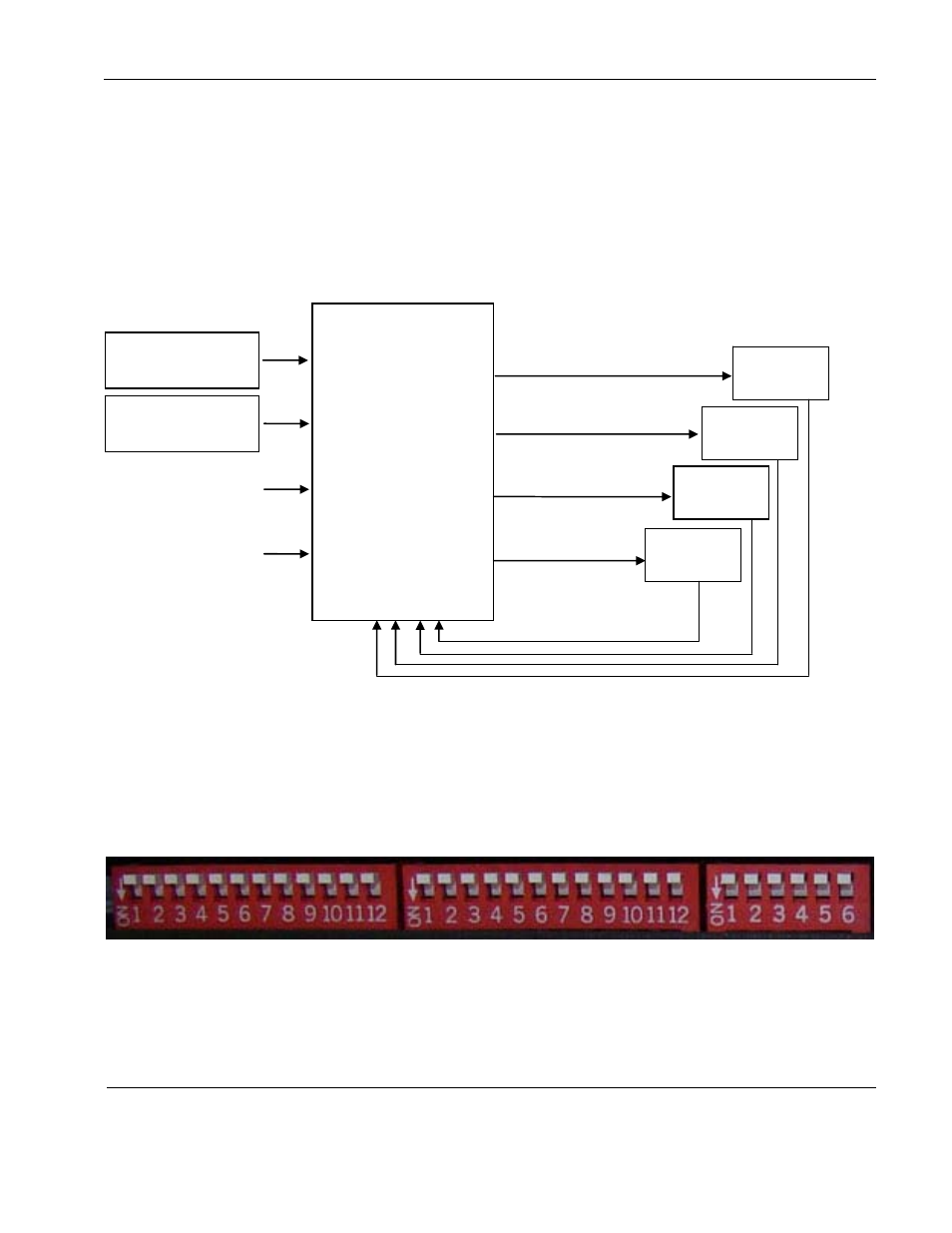
The following diagrams illustrate different ways to configure the unit’s connections to integrate
video control into an in-flight entertainment system.
SOURCE A
DVD PLAYER
Composite video out
ROSENVIEW LX
Composite video out
SOURCE B
SOURCE C
SOURCE D
N/A
VIDEO DISTRIBUTION
AMPLIFIER
N/A
COMPOSITE OUTPUT 1
MONITOR
1
MONITOR
2
MONITOR
3
MONITOR
4
SS1 SS2 SS3 SS4
Composite Select Switches
COMPOSITE OUTPUT 2
COMPOSITE OUTPUT 3
COMPOSITE OUTPUT 4
*SS = Source select switch
Example 1
– The
aircraft has four monitors. Each monitor has a composite video signal and a
source select switch. There are two composite video sources in the system. Each monitor can
play either source. No video briefing is provided.
Configure the DIP switches on the Video Distribution Amp as shown above. Leave all other
unused switches in the OFF position.
All switches are off because the monitors are in switched mode for sources A & B, and there
are no briefings or RGB sources. The AGC is on.
Document Number: 101720
Revision: A
Date: 10/14/08
Template: 4.2.3-6-FM; Revision A; 16 May, 2005
Page 14 of 16