Operating modes, Configuration dip switches, Rosen aviation 2.2. operating modes – Rosen Aviation 0700-006 : Video Distribution Amplifier User Manual
Page 6
Rosen Aviation
2.2. Operating Modes
Each video output may be configured to one of two modes of operation by setting the DIP
switches according to the ON indicators on the Video Distribution Amplifier.
Fixed mode Keeps the video output set to a specific input source—either composite input
B, C, or D, or RGB input A or B.
Switched mode Allows the user to select video input sources with a source select switch.
Each output may be configured independently of the other outputs.
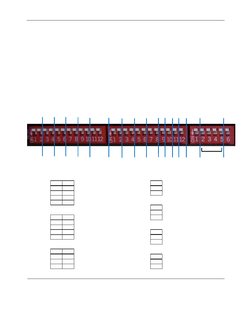
3. CONFIGURATION DIP SWITCHES
The configuration DIP switches are divided into three banks—left, middle, and right. Working from left
to right, configure the switches to set the video output for all monitors. Composite video output uses
paired switches. Figure 3 shows the switches that control each output and the other functions.
Figure 2 The factory default DIP switch setting is OFF (up)
RGB
Brief
Enable
Comp
Out 6
Comp
Out 4
Comp
Out 3
Auto
Gain
Control
NOT
USED
Comp
Brief
RGB
1
RGB
2
RGB
Brief
RGB
3
Comp
Enable
(C & D)
Comp
Out 7
Comp
Out 8
Comp
Out 5
Comp
Out 2
Comp
Out 1
The following tables show the pairs of switch positions for the various video and briefing outputs.
Composite Outputs 1 ‐ 8 (Left bank & Middle SW1‐SW4)
RGB 1, RGB 2, RGB 3 (Middle SW9‐SW11)
Source A or switched mode
Source A or switched mode
Source B fixed
Source B fixed
Source C fixed
Source D fixed
RGB Briefing Input Select (Middle SW12)
Composite Briefing Input Select (Middle SW5, SW6)
Source A Briefing
Source B Briefing
Source A Briefing
Source B Briefing
RGB Briefing Enable (Right SW1)
Source C Briefing
Source D Briefing
Briefing disabled
Briefing enabled
Composite Enable ‐ C & D (Middle SW7, SW8)
Automatic Gain Control ( AGC) (Right SW6)
Source A & B available
Source A, B, C, & D available
AGC enabled
Source A, B, & C available
AGC disabled
*SW7 can be either OFF or ON
ON
OFF
ON
SW 1
SW 2
OFF
OFF
OFF
ON
SW 1
SW 2
OFF
OFF
ON
ON
ON
OFF
ON
SW 1
SW 2
OFF
ON
ON
OFF
OFF
OFF
N/A*
ON
ON
SW
OFF
ON
SW
OFF
ON
SW
OFF
ON
SW
OFF
Document Number: 101720
Revision: A
Date: 10/14/08
Template: 4.2.3-6-FM; Revision A; 16 May, 2005
Page 6 of 16