Rosen aviation – Rosen Aviation 0700-006 : Video Distribution Amplifier User Manual
Page 16
Rosen Aviation
Document Number: 101720
Revision: A
Date: 10/14/08
Template: 4.2.3-6-FM; Revision A; 16 May, 2005
Page 16 of 16
SOURCE A
DVD PLAYER 1
Composite video out
ROSENVIEW LXM
RGB video out
SOURCE B
SOURCE C
RGB SOURCE A
VIDEO DISTRIBUTION
AMPLIFIER
MONITOR
5
MONITOR
6
MONITOR
4
MONITOR
8
SS5 SS6 SS7 SS8
Composite Select Switches
DVD PLAYER 2
Composite video out
COMPOSITE OUTPUT 5
COMPOSITE OUTPUT 6
COMPOSITE OUTPUT 7
COMPOSITE OUTPUT 8
BULKHEAD
MONITOR
(RGB)
DVD PLAYER 3
Composite video out
Video Briefing
RGB video out
RGB SOURCE B
RGB OUTPUT 1
MONITOR
7
BRIEFING ACTIVE
DISCRETE INPUT
MONITOR
1
COMPOS
MONITOR
3
MONITOR
2
COMPOSITE OUTPUT 4
COMPOSITE OUTPUT 3
COMPOSITE OUTPUT 2
ITE OUTPUT 1
SOURCE D
Video Briefing
Composite video out
*SS = Source select switch
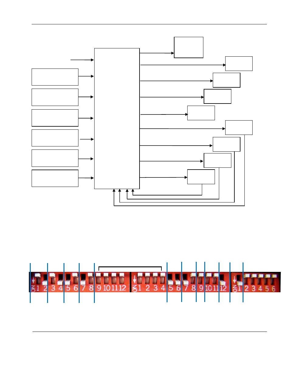
Example 3 – The aircraft has nine monitors. There are four composite video sources and two
RGB sources in the system. Monitors 1 and 2 have access to DVD player 2 only. Monitors 3
and 4 have access to DVD player 3 only. Monitors 5-8 have access to DVD players 1, 2, & 3
and have a source select switch. The RGB video and RGB briefing are displayed on the
bulkhead monitor. The AGC is on.
Comp
Enable
A-C
Comp
Brief
D
RGB
Brief
B
RGB
1
RGB
Brief
ON
Comp
Out
B
Comp
Out
C
Comp
Out
B
Comp
Out
C
Comp Out A
switched mode
Configure the DIP switches on the Video Distribution Amp as shown above. Leave all other
unused switches in the OFF position.