Configuring a video distribution amplifier, Installation example – Rosen Aviation 0700-006 : Video Distribution Amplifier User Manual
Page 10
Rosen Aviation
4.6. Configuring a Video Distribution Amplifier
We recommend using the following approach for a successful configuration:
• Turn
power
ON and verify that the power status LED on the VDA is green.
• Configure the DIP switches in a left-to-right order.
• Leave any switches turned OFF that you do not use.
• Cycle the 28V power after setting the configuration switches to ensure that all switches
remain on the last switched settings.
4.6.1. Installation Example
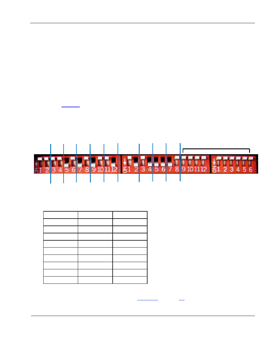
You can mix the video control and configure each output differently, as shown in
Composite outputs 1-2 are set to switched mode and they have a choice of video
inputs A-C. Outputs 3-5 are set to input source C, they do not have a source select
switch. Outputs 6-8 are set to input source B, they do not have a source select switch.
A composite briefing is set to input source D and there is a Briefing Active Discrete
Input.
Comp
Brief
Comp
Out 3
Comp
Out 2
Comp
Out 5
Comp
Out 7
Comp
Out 4
Comp
Out 6
Comp
Out 8
Comp
Enable
A-C
Not used in this example
Comp
Out 1
Figure 3 Mixed video control configuration
Table 9 Modes and sources for mixed video example
Output
Mode
Sources Used
Comp Out 1
Switched
A
Comp Out 2
Switched
A
Comp Out 3
Fixed
C
Comp Out 4
Fixed
C
Comp Out 5
Fixed
C
Comp Out 6
Fixed
B
Comp Out 7
Fixed
B
Comp Out 8
Fixed
B
Comp Briefing
N/A
D
Outputs 3-5 are set to input Source C.
Outputs 6-8 are set to input Source B.
Outputs 3-8 do not have source select
switches.
Only outputs 1-2, which are set to switched
mode (OFF/OFF), can use a source select
switch.
Composite Enable is set to ON/OFF to
select between the three video sources,
reserving Source D for the briefing.
For more configuration examples, see the
on page
Document Number: 101720
Revision: A
Date: 10/14/08
Template: 4.2.3-6-FM; Revision A; 16 May, 2005
Page 10 of 16