RIGOL DS6000 Series User Manual
Page 34
RIGOL
4
RP1001C User’s Guide
otherwise, the change of the position of the probe will cause the
DC drift. When measuring AC signals, users can move the current
probe.
4
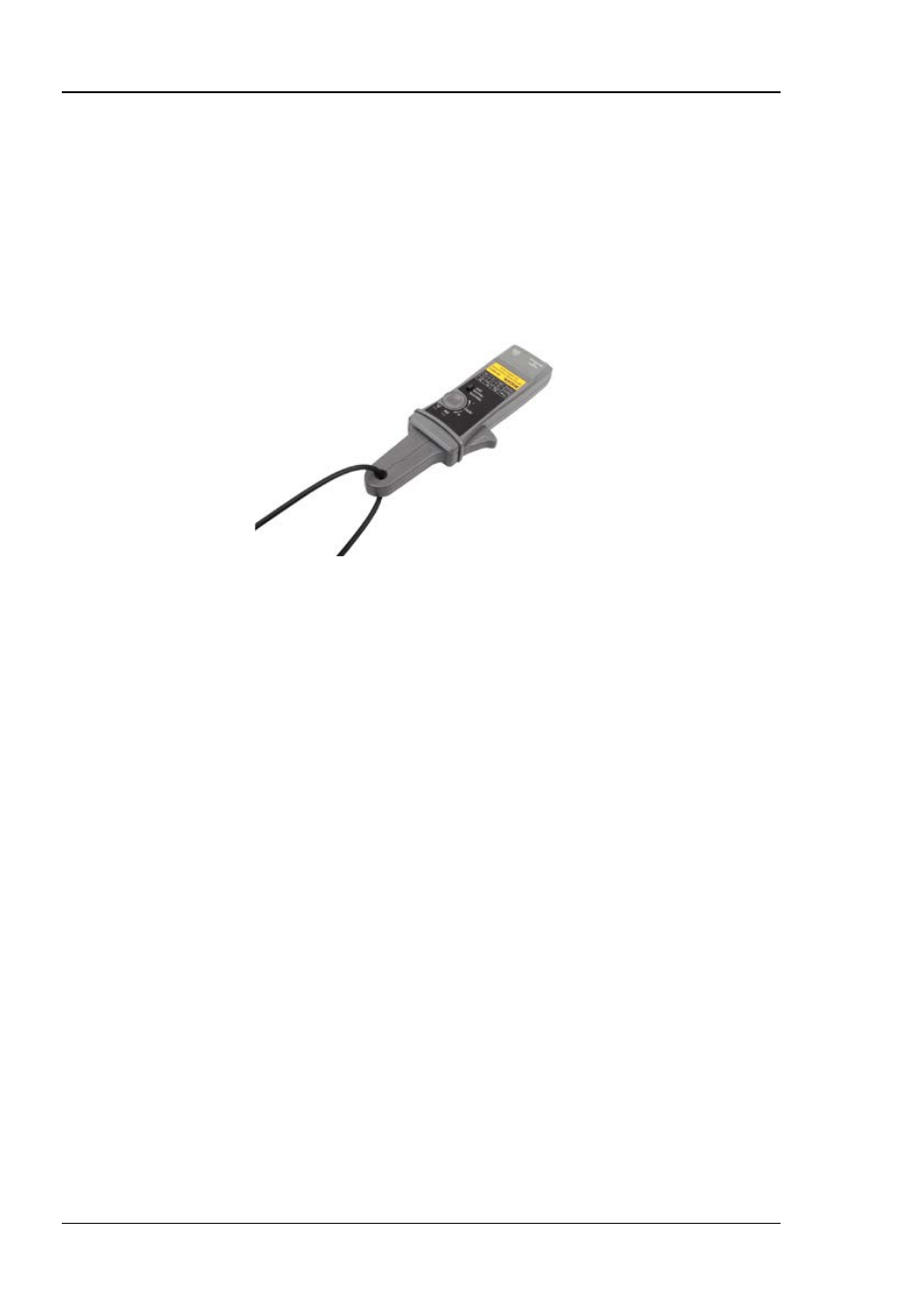
Before connecting the current probe to circuit, open the test
clamp and clamp it onto the conductor as shown in the figure
below.
Figure 2 Connection between the Test Clamp and Conductor
5
Adjust the probe channel and oscilloscope as necessary to get a
clear and stable view of the signal. At this point, you can see both
the current components of AC and DC. Set the coupling mode of
the oscilloscope to AC to see the current components of AC. The
operation method of the current components of AC is the ratio of
the voltage amplitude measured through the oscilloscope and
the switch range currently selected of the current probe (10
mV/A or 100 mV/A).
Note: The current drawn by different devices look much different
than that of others. While the RMS current can only be used in
low frequency current, the momentary peaks may be quite high.
The figure on the next page shows the difference between the
line current drawn by a resistive load and a motor controller.