Description – Remote Processing RPC-330 User Manual
Page 46
ANALOG OUTPUT
SECTION 14
Page 14-1 RPC -330
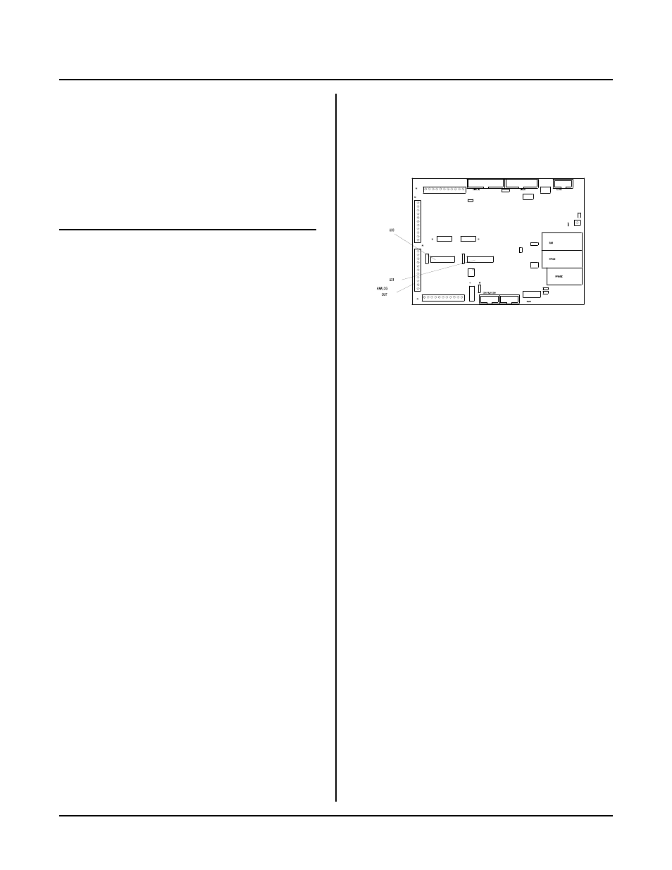
Figure 14-1 Analog Output
DESCRIPTION
Two optional analog output channels are available. They
can be configured to operate in one of three voltage
ranges. V oltage ranges are jumpered in hardw are using
W13 and W15. Outputs are located at P3 and are
designated as VO 0 and VO 1.
Voltage
Vo 0
Vo 1
Range
W13
W15
0 - 5V
[4-5]
[4-5]
0 - 10V
[1-2]
[1-2]
±5V
[2-3]
[2-3]
Installing a Channel
A MAX 508 or AD7248 converter (P/N 1354) is used as
the D/ A. Channe l 0 goes in socke t U20 and channel 1
goes in socket U21.
Before installing a chip, ground yourself and make sure
power is rem oved. Align pin 1 on the chip to pin 1 on
the socket. Pin 1 on both the socket and IC is marked
with either a "1", dot, or notch.
Output a Voltage
The AOT command is used to send data to an analog
output. T he syntax is:
AOT channel, value
channel specifies the analog channel to write data to and
is either a 0 or 1.
value is a number from 0 to 4095. The higher the
number, the mor e positive the output voltage.
The follow ing exam ples conver t a voltage to a num ber to
produc e an output.
AOT c,409.5 * v
0-10V range
AOT c,819 * v
0-5V range
AOT c,v*819 + 2047.5
±5V range
Noise Reduction
Analog outputs may be too noisy for some applications.
To reduce noise, simply add a 1 µF capacitor between
the output and ground.