Remote Processing RPC-330 User Manual
Page 22
DIGITAL I/O
SECTION 6
Page 6-1 RPC -330
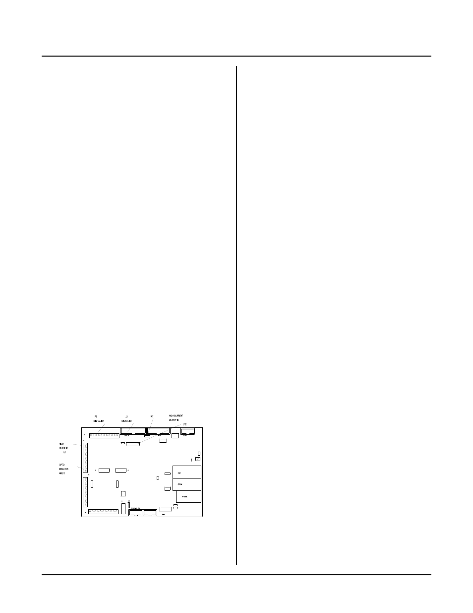
Figure 6-1 Digital I/O
INTRODUCTION
Digital I/ O lines ar e used to inter face with op to-module
racks, switches, low current LED's, and other TTL
d e vi ce s. T h e RP C - 33 0 ha s 3 4 o f t he se li ne s. 8 T T L I/ O
lines go to a terminal strip. 24 to an IDC connector.
Additionally, there is one high current output and an
opto-isolated input. Refer to the figure below for the
location of these lines.
Eight lines at P6 are intended for general purpose TTL
I/O such as switches, level sensors or to drive other
devices.
A 24 line con nector, J3, is inte nded to inter face to opto
racks or other TT L devices. 8 of these lines are high
curr ent outputs, capable of sink ing 75 to 200 m a. O pto
modules sense presence of AC or D C voltages or switch
t he m .
L8 at P2 is a "zero" ohm FE T switch. It is intended for
switching L ED b ack lighting on a n LC D display. This
line may also be used to switch high current, high
voltage power . It can sw itch up to 2 amps.
INT 0 and INT 1 at P2 and P3 may be used as input
lines provided that they are not used as interrupt lines.
Hardw are counters may not be configured to interrupt
when these lines are inputs.
ISOA/B at P2 may be used as an isolated input or an
interrupt for INT 0.
In addition to the 24 I/O lines from J3, the display port
can be used as digital I/O. Refer to Section 8 for more
information.
WARNING:
Apply power to the RPC -330 before applying a
voltage to the digital I/O lines to prevent current
from flowing in and damaging devices. If you
cannot apply power to the RPC-330 first, contact
technical support for suggestions appropriate to your
application. Power may be applied to ISOA/B at
any time.
Several softwar e comm ands support the digital I/O ports.
ON L INE br anches to a subroutine w hen a line changes.
ON C OUN T counts the number of high to low
transitions at a digital line. Maxim um coun ting rate is
about 95 Hz. T hese commands simplify design and
greatly speed up execution. See Appendix A for more
information.
DIGITAL I/O PORTS
All ports use an 82C55 for I/O. Lines are accessed
using the LINE or L INEB comm ands. Lines at J3 and
P6 are configured for inputs or outputs using the
CON FIG LIN E comm and.
WARNING:
When configuring lines for outputs using CONF IG
LINE, lines go low momentarily (less than 10
micro-seconds) until they are set high again per the
data in the command line. Some other lines are
affected when CONFIG LIN E 0 is executed. Refer
to CONF IG LINE command in Appendix A for
more inform ation.
Digital Por t J3
This port is used to interface opto modules (using MPS
series racks), dr ive small relays, solenoids, m otors, or
lamps, and provide general purpose TTL I/O to other
logic devices or mechanical switches. J3 pin out is at the
end of this section.
The lines on J3 are divided into 3 eight bit groups from
an 82C55. Ports A and B are configured as all inputs or
outputs. Port C is progr amm ed as one gr oup of 8 inputs
or outputs or as two groups of four lines (upper and
lower C). T he four lines in upper and lower C can each
be prog ram med as a ll inputs or outp uts. R efer to T able
6-1 to determine the opto channel or J3 pin number for a
port. Use C ONF IG LIN E 100 (A ppendix A ) to
configure por ts A, B, and C for inputs or outputs.
When a line is configured as an output, it can sink a