Amplifiers, Calibration, Commands – Remote Processing RPC-330 User Manual
Page 39
ANALOG INPUT
SECTION 10
Page 10-5 RPC -330
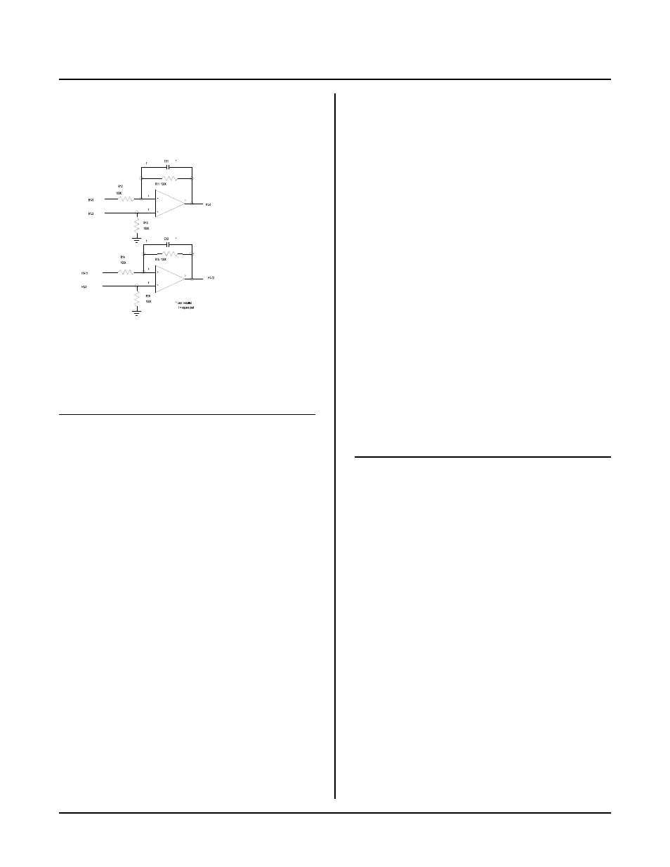
Figure 10-2 Amplifier Circuit
AMPLIFIERS
Two operational amplifiers are available to signal
condition inputs.
Amplifiers are accessed through header connector H1.
Pin out is as follows:
H1 pin
Function
1
Temper ature output from U14
2
To channel 0 analog input
3
Non-inverting input, amplifier A
4
Output from amplifier A
5
Inverting input, amplifier A
6
Appr oximately + 12V supp ly
7
Ground
8
Ground
9
Non-inverting input, amplifier B
10
Appr oximately -12V supp ly
11
Inverting input, amplifier A
12
Output from amplifier A
13
5.000 V r eference output
14
Ground
Voltage outputs from pins 6 and 10 are generated by the
RS-232 chip U8. These voltages go to 0 volts when
operating the board in IDLE m odes 1 or 2.
CALIBRATION
The A /D comes fa ctory ca librated for a 0 to 5V inpu t.
This range is chan ged by adjusting R17. You can adjust
the range to 5.12V. This is useful when the input is 0 -
5V and you want to know when the input is over-range.
To calibrate or adjust the voltage reference:
1.
Connect the voltmeter ground to a GN D point
on the Analog IN terminal strip. Make sure
there are no other connections to the analog
ground.
2.
Connect the voltmeter ' + ' lead to U14, pin 6.
3.
Adjust R5 for 5.00 VDC or other voltage as
desired. D o not exceed 5.2 or go below 4. 8
volts.
COMMANDS
The following RPBASIC-52 com mands are used for
analog input. Mor e inform ation is found in the appendix
of this manu al.
Comm and
Function
AIN(n)
Returns analog value.
CON FIG AIN (n)
Configures analog input
channels