RISCO Group iWISE DT PET User Manual
Page 2
Especi
¿caciones Técnicas
Eléctricas
Consumo de corriente
16mA a 12VCC (Típico)
41mA a 12VCC (Máx.)
Requisitos de voltaje
10-16VCC
Contactos de Alarma
24VCC, 0.1A
Contactos de Tamper
24VCC, 0.1A
Ambientales
Inmunidad a RF
Según EN50130-4
Temperatura de funcionamiento -10ºC a 55ºC (14F a 131F)
Temperatura de almacenamiento -20ºC
a
60ºC (-4F a 140F)
Óptica
Filtrado
Protección contra luz blanca
Físicas
Tamaño
127.6 x 64.2 x 46.6 mm
(5 x 2.5 x 1.84 pul)
Peso
120 gr. (4.2 oz.)
Prova di movimento (Walk Test)
1. Due o tre minuti dopo aver alimentato il rivelatore (preriscaldamento)
effettuare la prova di copertura dell’area da proteggere veri¿cando
la risposta del rivelatore tramite l’accensione dei LED (vedere Figura 4).
2. La portata della microonda va regolata tramite l’apposito
potenziometro situato sulla scheda elettronica. Regolare il
potenziometro della microonda al minimo possibile riferito all’area da
proteggere.
Regolazione Portata MW (vedere Figura 5)
LED Stato Descrizione
LED
Stato Descrizione
Giallo
Illuminato
Rilevazione del canale PIR
Verde
Illuminato
Rilevazione del canale MW
Rosso
Illuminato
ALLARME
Tutti i
LED
Lampeggiante
(consecutiva-
mente)
All’alimentazione tutti i LED lampeggiano
in sequenza
¿no alla ¿ne del periodo di
preriscaldamento (2-3 minuti).
Speci
¿che Tecniche
3 Regolazione Alta
1 Regolazione Bassa
A Rivelatore
2 Regolazione corretta
B Corridoio
MIN MAX
iWISE 811DTPT
iWISE 811DTPT è un rivelatore che discrimina gli animali domestici
(45 kg - 100lbs) garantendo una ottima rilevazione degli intrusi.
Tramite algoritmi proprietari e lenti appositamente progettate
iWISE 811DTPT discrimina gli impulsi infrarossi generati dagli animali
domestici ignorando questi segnali e generando l'allarme solo in caso
in cui l'area protetta sia stata violata da un intruso. Questo rivelatore
permette di inserire l'impianto d'allarme pur avendo un animale
domestico in casa evitando di generare allarmi impropri.
Installazione / Manutenzione
1. Installazione - iWISE 811DTPT può essere installato sia su di
una super¿cie piana che ad angolo.
Per ottimizzare la discriminazione degli animali seguire
rigorosamente le seguenti regole:
• Installare il rivelatore verticalmente alla corretta angolazione
riferita al pavimento.
• Per una corretta immunità agli animali montare il rivelatore
ad un altezza di 2.1m con la lente RL111H e 2.4m con la
lente RL108PTH.
• Assicurarsi che l'animale non possa superare l'altezza di
1.5 m. saltando su mobili o mensole.
• Non montare l'unità di fronte a scale interne accessibili
dall'animale.
2. Utilizzando uno strumento appropriato aprire i fori a sfondare, di
seguito elencati, della base del contenitore come illustrato in
Figura 1.
3. Veri¿care la posizione verticale della scheda elettronica su "L"
(sul lato sinistro in basso della scheda elettronica).
4. Impostare i microinterruttori (vedi impostazione dei
microinterruttori).
5. Rimontare il coperchio frontale e stringere la vite di blocco
coperchio.
6. Effettuare una prova di copertura (Sezione Prova di movimento).
7. Sostituzione delle Lenti (vedere Figura 2).
Nota:
Non è applicabile in questa versione il tamper antirimozione
tramite "la linguetta" posta sulla base del contenitore.
Cablaggio Morsettiera (vedere Figura 3)
Morsetto
Descrizione
- 12 +
Ingresso di alimentazione 12V
ALARM
Relé N.C.
TAMPER
Interruttore N.C.
Predisposizione Microinterruttori e Ponticelli
Microint./Pontic.
Funzione
SW1-1: LEDS
Usato per abilitare o disabilitare il
funzionamento dei LED.
I LED sono abilitati
ON (Default)
Sleeve
Cut
Corners
Short Pin
(Facing upwards)
Lens
Figure 2.
Lens Replacement
1
2
3
A
B
Figure 5.
MW range adjustment
Figure 3.
Terminal Wiring
12VDC
+ 12 -
ALARM
TAMPER
Filtro
Protezione contro le luci bianche
Dimensioni
127.6 x 64.2 x 46.6 mm
Peso
120 gr.
Contatti Tamper
24V
-, 0.1A
Immunità RF
Secondo EN50130-4
Temp. funzionamento
da -10ºC a 55ºC
Temp. stoccaggio
da -20ºC a 60ºC
Assorbimento di corrente
16mA a 12V
- (Nominale)
41mA at 12V
- (Massimo)
Alimentazione richiesta
da 10V
- a 16V-
Contatti di allarme
24V
-, 0.1A
Ottica
Fisiche
Elettriche
Ambientali
Range
Adjustment Bolt
Thread
Back tamper
“Breakable” plate -
Not applicable in this version
Figure 1.
Back cover - Knockouts
Físicas
Tamanho
127.6 x 64.2 x 46.6 mm
(5 x 2.5 x 1.84 pol.)
Peso
120 gr. (4.2 oz.)
Ajustes dos Dipswitch’s
Jumper
Função
SW1-1: LED
Usado para determinar a operação dos LEDs do
detector.
ON
(Predeterm.)
Os LEDs estão habilitados
OFF
LEDs estão desativados.
SW1-2
Sensibilidade
De
¿ne a sensibilidade do detector Infravermelho
Passivo
ON
OFF
(Predeterm.)
iWISE 811DTPT
O iWISE 811DTPT proporciona completa imunidade a animais de
pequeno porte (45 kg - 100 lbs) sem prejuízo no desempenho de captura.
O modelo iWISE 811DTPT distingue facilmente entre intrusos e animais
de pequeno porte, permitindo aos animais completa liberdade de
movimento, sem falsos alarmes.
Instalação / Manutenção
1. Montagem - O iWISE 811DTPT pode ser montado em uma
superfície plana ou num canto da parede (montagem de canto)
A ¿m de melhorar a imunidade à animais de pequeno porte, as
seguintes diretivas são recomendadas:
• Monte o detector verticalmente, em ângulos retos em relação
ao chão.
• Para melhorar a imunidade à animais de pequeno porte monte
o sensor a uma altura de 2.1m (6’11”) com a lente RL111H e
2.4m (7'11") com a lente RL108PTH.
• Assegure- se de que um animal não possa chegar acima da
altura de 1.5 m (5’), saltando em móveis ou prateleiras.
Alta sensibilidade
Baixa sensibilidade
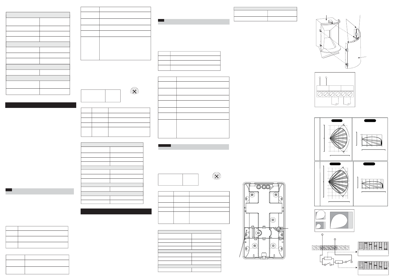
RL 111H
F e e t
0
1 0
0
4
6
8
10 11
2
0
2
4
0
1 0
2 0
3 0
4 0
Meters
Feet
Meters
Feet
Meters
Feet
Meters
Feet
2 0
90°
0
1 0
2 0
3 0
1 0
2 0
3 0
F e e t
0
2
4
6
8
2
4
6
8
0
2
4
6
8 10 11
0
1 0
2 0
3 0
4 0
SIDE VIEW
TOP VIEW
Figure 4.
iWISE 811DTPT Lenses and Microwave Range
RL 108PTH
F e e t
0
1 0
0
4
6
8
2
0
2
4
2 0
0
1 0
2 0
3 0
SIDE VIEW
2 0
0
1 0
2 0
1 0
F e e t
0
2
4
6
2
4
6
0
2
4
6
8
0
1 0
2 0
3 0
TOP VIEW
90°
SW1-2 sens
Utilizzati per determinare la sensibilità del
Canale PIR
OFF (Default)
Bassa sensibilità
Microint./Pontic.
Funzione
OFF
I LED sono disabilitati. Non è possibile
alcun controllo remoto.
ON
Alta sensibilità
RISCO Group Limited Warranty
RISCO Group and its subsidiaries and af
¿liates ("Seller") warrants its products to
be free from defects in materials and workmanship under normal use for 24
months from the date of production. Because Seller does not install or connect the
product and because the product may be used in conjunction with products not
manufactured by the Seller, Seller cannot guarantee the performance of the
security system which uses this product. Seller's obligation and liability under this
warranty is expressly limited to repairing and replacing, at Seller's option, within a
reasonable time after the date of delivery, any product not meeting the
speci
¿cations. Seller makes no other warranty, expressed or implied, and makes
no warranty of merchantability or of
¿tness for any particular purpose. In no case
shall seller be liable for any consequential or incidental damages for breach of this
or any other warranty, expressed or implied, or upon any other basis of liability
whatsoever.
Seller's obligation under this warranty shall not include any transportation charges
or costs of installation or any liability for direct, indirect, or consequential damages
or delay. Seller does not represent that its product may not be compromised or
circumvented; that the product will prevent any personal injury or property loss by
burglary, robbery,
¿re or otherwise; or that the product will in all cases provide
adequate warning or protection. Seller, in no event shall be liable for any direct or
indirect damages or any other losses occurred due to any type of tampering,
whether intentional or unintentional such as masking, painting or spraying on the
lenses, mirrors or any other part of the detector. Buyer understands that a
properly installed and maintained alarm may only reduce the risk of burglary,
robbery or
¿re without warning, but is not insurance or a guaranty that such event
will not occur or that there will be no personal injury or property loss as a result
thereof. Consequently seller shall have no liability for any personal injury, property
damage or loss based on a claim that the product fails to give warning. However,
if seller is held liable, whether directly or indirectly, for any loss or damage arising
under this limited warranty or otherwise, regardless of cause or origin, seller's
maximum liability shall not exceed the purchase price of the product, which shall
be complete and exclusive remedy against seller. No employee or representative
of Seller is authorized to change this warranty in any way or grant any other
warranty.
WARNING: This product should be tested at least once a week.
CAUTION: risk of explosion if battery is replaced by an incorrect type.
Dispose of used batteriess according to local regulations.
RISCO Group Contacting Info
RISCO Group is committed to customer service and product support. You can
contact us through our website (www.riscogroup.com) or at the following
telephone and fax numbers:
I ponticelli J1 e J2 permettono la selezione dei
valori resistivi da assegnare ai circuiti di Tamper e
di Allarme (1K, 2.2K, 4.7K, 5.6K, 6.8K) in funzione
della centrale d’allarme utilizzata (vedere la
Figura 6 in basso).
Seguire lo schema di collegamento dei morsetti
illustrato in Figura 6 quando si vuole collegare il
sensore ad una centrale d’allarme usando il doppio
bilanciamento resistivo (DEOL).
J1 - Alarm EOL
J2 - Tamper EOL
Os jumpers J1 e J2 permitem a seleção da
resistência do Tamper e do Alarme (1K, 2.2K, 4.7K,
5.6K, 6.8K) de acordo com o painel de controle
(ver Figura 6 abaixo).
Siga o diagrama de conexão do bloco de terminais
na Figura 6, ao conectar o detector a uma Zona
de Duplo Fim-de-Linha (DEOL).
J1 - Alarm EOL
J2 - Tamper EOL
Figure 6.
Schematic of EOL Resistors
Tamper / Alarm EOL Jumpers
No
Resistor
(Factory Settings)
1K
2.2K
4.7K
5.6K
6.8K
J1 - ALARM EOL JUMPERS
J2 - TAMPER EOL JUMPERS
No
Resistor
(Factory Settings)
1K
2.2K
4.7K
5.6K
6.8K
PANEL DEOL
+12-
ALARM TAMPER FAULT/AM
LED
ALARM
TAMPER
UK Tel: +44-161-655-5500 E-mail: [email protected]
ITALY Tel: +39-02-66590054 E-mail: [email protected]
SPAIN Tel: +34-91-490-2133 E-mail: [email protected]
FRANCE Tel: +33-164-73-28-50 E-mail: [email protected]
BELGIUM Tel: +32-2522-7622 E-mail: [email protected]
U.S.A Tel: +1-631-719-4400 E-mail: [email protected]
BRAZIL Tel: +55-11-3661-8767 E-mail: [email protected]
CHINA (Shanghai) Tel: +86-21-52-39-0066
E-mail:
CHINA (Shenzhen) Tel: +86-755-82789285
E-mail:
SINGAPORE Tel: + 65-66222388 E-mail: [email protected]
POLAND Tel: +48-22-500-28-40 E-mail: [email protected]
ISRAEL Tel: +972-3-963-7777 E-mail: [email protected]
MIN MAX
Teste de Caminhada
1. Dois minutos depois de ativar (período de aquecimento),
caminhe para testar o Detector através de toda a área protegida
para veri¿car a correta operação da unidade (ver Figura 4).
2. O alcance de Microondas deve ser ajustado usando-se o
potenciômetro, que está localizado no PCB. É importante colocar
o potenciômetro na con¿guração mais baixa possível que ainda
possa proporcionar su¿ciente cobertura para toda a área protegida.
Ajuste do Alcance do Microondas (ver Figura 5)
1 Energia em excesso
2 Energia fraca
3 Ajuste correto
A Detector
B Corredor
Especi
¿cações Técnicas
Elétricas
Consumo de Corrente
16mA a 12VDC (Típico)
41mA a 12VDC (Máx.)
Requisitos de voltagem
10 -16VDC
Contatos de alarme
24VDC, 0.1A
Contatos de Tamper
24VDC, 0.1A
Ambientais
Imunidade a RF
De acordo com EN50130-4
Temperatura de operação
-10C a 55C (14F a 131F)
Temperatura de armazenamento
-20C a 60C (-4F a 140F)
Ótica
Filtragem
Proteção contra luz branca
Terminais de Fiação (ver. Figura 3)
Terminal
Descrição
- 12 +
Entrada de 12VDC
ALARME
Relé N.F.
TAMPER
Chave do tamper N.F.
Verde
Aceso
Detecção no Microondas
Vermelho
Aceso
ALARME
Todos os
LEDs
Piscando
(sucessiva-
mente)
Ao conectar, os LEDs piscarão
consecutivamente até o
¿nal do período
de aquecimento (2-3 minutos). Ao
¿nal do período de aquecimento.
Visualização dos LEDs
LED
Estado
Descrição
Amarelo
Aceso
Detecção de Infravermelho
Passivo
Nota:
O Tamper de Parede com "chapa destacável" não se aplica
essa versão.
• Não monte o aparelho em frente a degraus aos quais o animal
pode ter acesso.
2. Usando uma ferramenta apropriada, abra os seguintes furos
pré-marcados na base do detector (ver Figura 1).
3. Assegure que a posição vertical da PCB está na marca “L” (na
parte inferior esquerdo da PCB)
4. Ajuste as chaves DIP switch (observe o Ajuste dos DIP switch)
5. Recoloque a tampa dianteira em seu lugar (na seqüência contrária
à da remoção)
6. Realize um teste de Caminhada (ver a seção Teste de Caminhada).
7. Troca de Lentes (ver. Figura 2).
Importante:
As distâncias podem variar de acordo com as condições
térmicas ambientais.
I T A L I A N O
P O R T U G U Ê S