Consolidator monitor software – Precision Digital PD941 User Manual
Page 52
ConsoliDator Multi-Channel Controller
Instruction Manual
52
CONSOLIDATOR MONITOR SOFTWARE
Each ConsoliDator is shipped with PC software on CD-ROM, which supports monitoring,
data logging and controller setup/programming. You may also download this software from
the web at www.predig.com. There are separate versions of the software for 4-channel and
8-channel models.
Connecting to PC
Many computers are equipped with at least one 9-pin serial port compatible with RS-232.
For distances up to approximately 50 ft, a null-modem cable is adequate. The null modem
cable looks similar to a standard serial cable, except both ends are female, and the
transmit and receive lines in the cable cross-over unlike a standard serial cable. Reference
Serial Communication Connections (page 19) for more information.
Installing Software
Load the ConsoliDator Software CD-ROM into your CD-ROM drive. If the installation does
not load automatically within a few moments, click on the Start button on the Windows®
taskbar, then click RUN. Type x:\ ConsoliDator_ Monitoring_System.exe (where x is your
actual CD-ROM drive letter) and press enter. Follow on-screen instructions.
Using ConsoliDator Monitor Software
Launch the program from the Start menu or desktop shortcut. Make sure you are using the
correct version of the software for the number of channels your model has – 4 or 8. Verify
the controller is powered up and properly connected before proceeding.
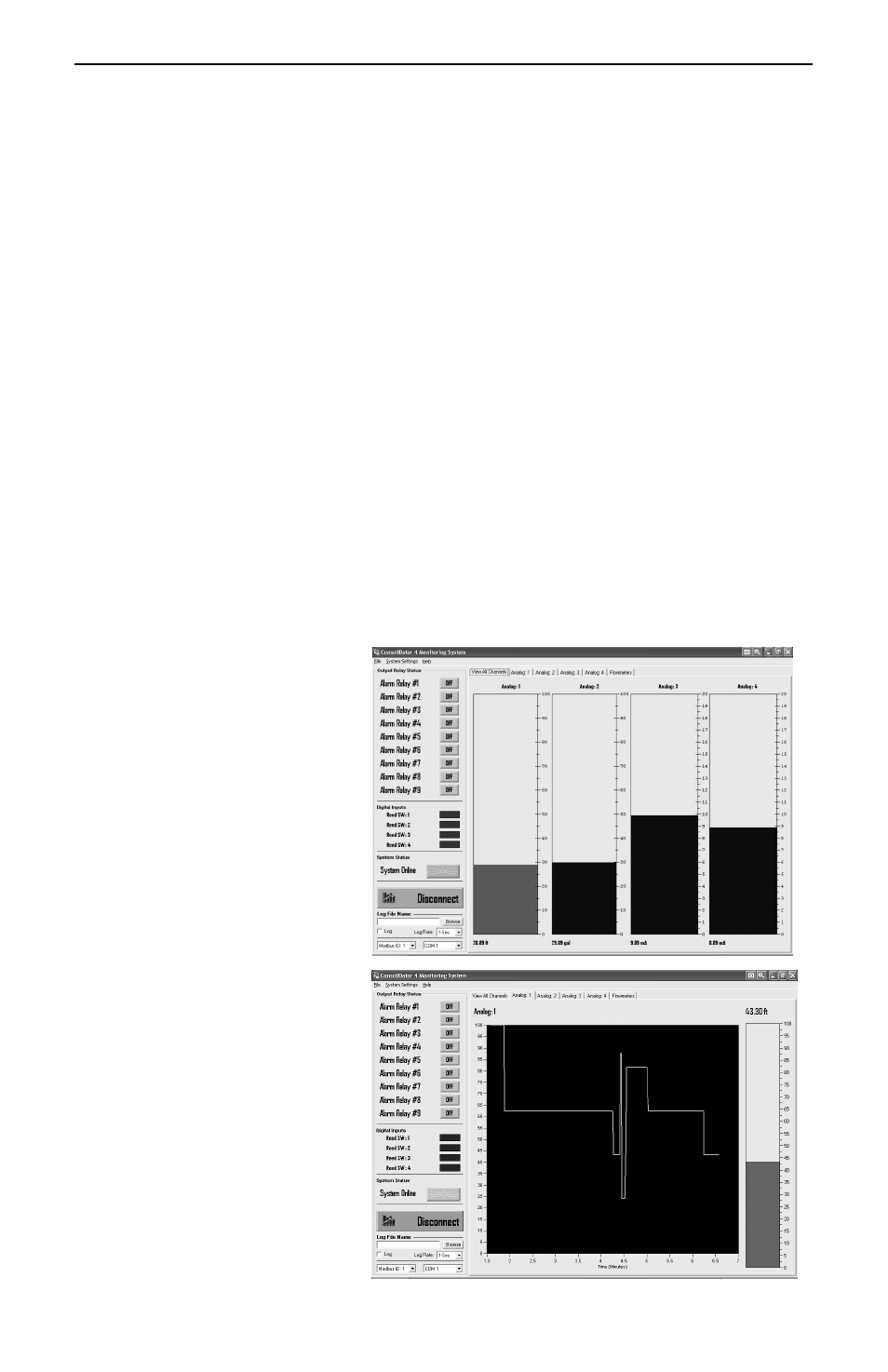
From the drop-down menu in the
bottom left of the screen, select
the Modbus ID that matches the
same setting in the controller.
Default is Modbus ID: 1. Click the
Connect button in the lower left
of the screen and allow a moment
for the software to read data in.
Window tabs above the
bargraphs navigate the various
channel displays available. The
screen in the top right is active
when the View All Channels tab
is selected. It shows all Analog
Input bargraphs and numeric
values along with Relay and
Digital Input status. This
information represents real time
data sent from the controller.
Selecting a tab for a specific
channel brings a chart of the style
shown in the bottom right. The
charts show a graphical history
for each Analog Input channel
along with its real time bargraph
and numeric value. There is also
a tab for the flow meter pulse
input channels, which shows
numeric total and numeric and
bargraph rate for all flow
channels.