Modbus, Serial communication, Modbus register tables – Precision Digital PD941 User Manual
Page 47
ConsoliDator Multi-Channel Controller
Instruction Manual
47
MODBUS
®
SERIAL COMMUNICATION
The controller is equipped with serial communication capability as a standard feature. Baud
Rate, Parity, Modbus ID (Address) and Transmit Delay are entered in the General
Functions box, which appears in the main setup menu. The baud rate and parity selected
must match the settings for all other devices on the network. Modbus ID must be unique so
it will not interfere with other devices.
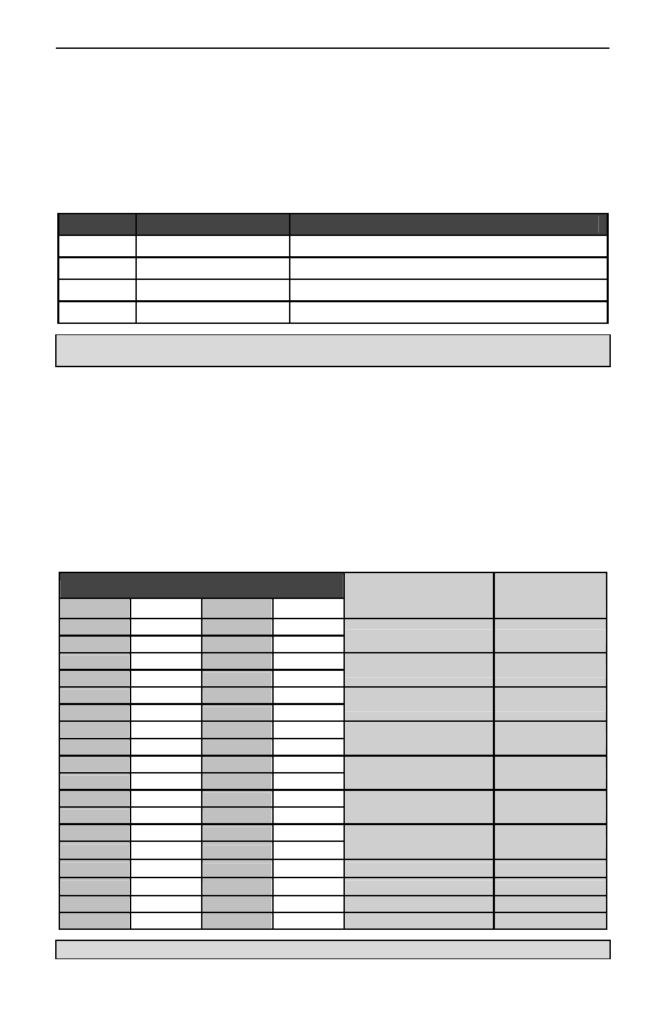
ConsoliDators support the following Modbus control functions:
Command
Name
Description
03
Read Holding Register
Read multiple bytes from holding registers.
05
Write Single Coil
Set single coil value control
06
Write Single Register
Set single value into specified holding register.
16
Write Multiple Registers
Set multiple values into specified holding registers.
Note: To save data to non-volatile memory after changing the contents of holding register(s) use the
Write Single Coil command [command code 05] to “ON” at address 64251.
To control the relays via MODBUS you would use the Write Single Coil command
[command code 05] and send either the “ON” or “OFF” to the appropriate alarm relay (1-9).
The ConsoliDator can also work as a "MODBUS Display" by setting the desired analog
input channel to the "FIXED" type and then over MODBUS change the "K-Factor/Modbus
Display" value for the corresponding channel. This input type is transparent to the rest of
the functions of the unit (i.e. relays, etc...). The value, once the EEPROM save command is
sent to the unit, is also maintained in EEPROM after the next power cycle.
Modbus Register Tables
Table 1. Analog Output Channels Register Addresses
Address (offset from 40000)
Description
Data Type
Ch. 1
Ch. 2
Ch. 3*
Ch. 4*
801
819
837 855
4 mA Value
Floating Point
802
820
838 856
803
821
839 857
20 mA Value
Floating Point
804
822
840 858
805
823
841 859
Set point Value
Floating Point
806
824
842 860
807
825
843 861
PID KP
Floating Point
808
826
844 862
809
827
845 863
PID KI
Floating Point
810
828
846 864
811
829
847 865
PID KD
Floating Point
812
830
848 866
813
831
849 867
PID Output Value
Floating Point
814
832
850 868
815
833
851 869
PID Cycle Time
Integer
816
834
852 870
Output Type
Byte
817
835
853 871
Input Ch.
Byte
818
836
854 872
PID Direction
Byte
*Channels 3-4 only apply to ConsoliDator 4 (PD940 & PD941) models.