Sealey VS0061 User Manual
Combustion leakage tester, Fig.1b fig.1a, Instructions for
1. SAFETY INSTRUCTIONS
2. INTRODUCTION
WARNING! Ensure all Health & Safety, local authority, and general workshop practice
regulations are strictly adhered to when using product.
WARNING! Ensure the radiator is cool before opening the cap.
Maintain tester in good and clean condition for best and safest performance.
DO NOT use tester
if damaged.
Wear suitable clothing to avoid snagging when working under the bonnet with the engine running.
DO NOT wear jewellery and tie back long hair.
Use proper ventilation and avoid breathing in exhaust fumes.
Keep a fire extinguisher to hand.
Account for all tools and parts being used and
DO NOT leave them in or near the engine.
Keep tester parts clean and dry and store each component part in its appropriate location in the
carry case.
Thick gloves must be worn when working with this tester to protect the operator from discharges
of steam from radiator or header tank.
Arms and wrists should also be covered.
Wear eye protection when using this product.
IMPORTANT: Always refer to the vehicle manufacturer’s service instructions, or proprietary
manual, to establish the current procedure for draining off coolant.
The VS0061.V2 combustion leakage test kit is designed to diagnose blown gaskets and cracked cylinder
heads quickly and easily by checking for the presence of CO² in the cooling system. If combustion
gasses are present, the colour of the test fluid changes from blue to yellow. The tester comes with a cone
adaptor or may be used in conjunction with radiator caps from the VS006 set. For a refill of test fluid
order Part No.VS0061F.3
INSTRUCTIONS FOR:
COMBUSTION LEAKAGE TESTER
MODEL:
VS0061.V2
Thank you for purchasing a Sealey product. Manufactured to a high standard this product will, if used according to these instructions and
properly maintained, give you years of trouble free performance.
IMPORTANT: PLEASE READ THESE INSTRUCTIONS CAREFULLY. NOTE THE SAFE OPERATIONAL REQUIREMENTS, WARNINGS, AND
CAUTIONS. USE THIS PRODUCT CORRECTLY, AND WITH CARE FOR THE PURPOSE FOR WHICH IT IS INTENDED. FAILURE TO DO SO
MAY CAUSE DAMAGE AND/OR PERSONAL INJURY AND WILL INVALIDATE THE WARRANTY.
3. OPERATING INSTRUCTIONS
3.1
PREPARATION
3.1.1 Remove approximately 1/10 of the volume of coolant from the radiator. Consult an appropriate
vehicle repair manual on the best method of doing this.
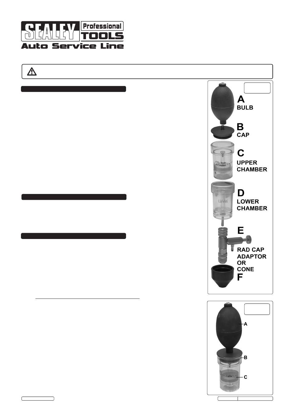
3.1.2 The various components of the tester are a push fit with the exception of the brass Rad Cap
Adaptor which has a ring at the top which allows it to be tightened onto the tube which
protrudes from the lower chamber. The two chambers are a close fit and may require a twisting
action to assemble them or get them apart.
3.1.3. The tester component parts, as shown in fig.1, can be configured in two main ways. See over
page.
3.2
RADIATOR/HEADER TANK ADAPTOR CONFIGURATION.
3.2.1 As shown in fig.2a the tester can be configured to fit onto a header tank or radiator using one of
the adaptors supplied with the VS006 pressure test kit. See fig.2b. When the tube on the lower
chamber ‘D’ is inserted into the brass adaptor ‘E’ ensure that the brass ring at the top of the
adaptor is tightened down so that it grips the tube. The brass adaptor ‘E’ will be a push fit onto
the radiator or header tank adaptor. Push down until it clicks into place. To release the assembly
pull the ring at the bottom of the brass adaptor upwards.
3.2.2 Fill the upper chamber with test fluid up to the dotted line.
3.2.3 Turn on the vehicle engine and wait for steam to enter the lower chamber.
3.2.4 When steam is visible in the lower chamber pump the rubber bulb several times to draw steam
into the upper chamber and observe the colour of the test fluid. If the fluid turns yellow this
indicates the presence of CO² in the coolant and the need to investigate further for a suspect
cylinder head gasket or cracked head.
3.2.5 Alternatively the tester can be used without the bulb attached as shown in fig.2c. In this
configuration the steam will automatically pass into the upper chamber. Take care to keep limbs
and face away from any jet of steam being expelled from the hole in the top of the cap.
3.2.6 As soon as the test is complete turn off the engine and allow the sytem to cool for a while. Before
removing the tester from the radiator or header tank open the tap on component ‘E’ to allow any
remaining pressurised steam to escape. Thick gloves must be worn during this process and
when the tester and adaptor are removed from the radiator.
fig.1b
fig.1a
© Jack Sealey Limited
VS0061.V2 Issue No.1 09/11/12
Original Language Version