Dram simm replacement procedure, Dram simm replacement, Procedure – Enterasys Networks Enterasys Gold Distributed Forwarding Engine 4H4285-49 User Manual
Page 77: Removing the network expansion module (nem), Offline/ reset
Gaining Access to Memory Modules
Matrix DFE-Gold Series PoE Module Hardware Installation Guide B-7
DRAM SIMM Replacement Procedure
After you have removed the safety cover as described in “
Removing the Network Expansion Module (NEM)”
.
Removing the Network Expansion Module (NEM)
Refer to
1.
Attach the antistatic wrist strap (refer to the instructions on the antistatic wrist strap
package).
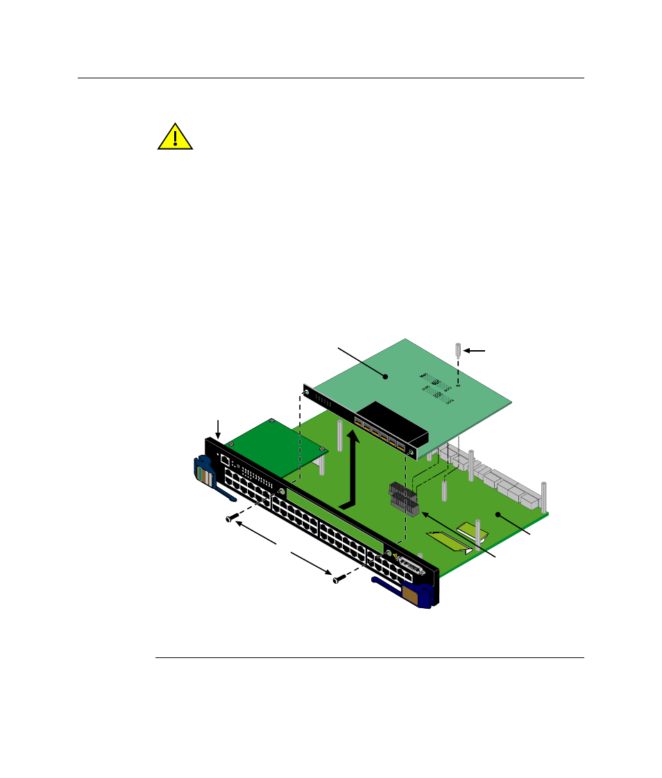
Figure B-4 Removing the Optional Network Expansion Module
Caution: Observe all Electrostatic Discharge (ESD) precautions when handling sensitive
electronic equipment.
Precaución: Al trabajar con equipos electrónicos sensibles, tome todas las precauciones
de seguridad para evitar descargas de electricidad estática.
1 Coverplate screws (2)
4 Standoff
2 NEM
5 Main PC board
3 DFE Module front panel
6 Main board connectors
1X
G R
O U
P
1
G R
O U
P
2
11X
13X
23X
OFFLINE/ RESET
COM
CPU
M
G
M
T
GR
OUP
SELECT
GR
OUP
1
2
3
4
5
6
7
8
9
10
11
12
POE
12
X
14X
24X
G R
O U
P
3
25X
35X
26X
36X
G R
O U
P
4
37X
47X
38X
48X
1
2
3
4
48V
---
20A
MAX
OPTIONAL
PO
WER INPUT
4H
42
zz
85
-4
9
FA
ST ENE
T
DFE
1
2
3
4
5
6
1
2
3
4
5
6
7G-6MGBIC-A
А
Б
В
Г
Е
Д