Memory locations and replacement procedures, Offline/ reset – Enterasys Networks Enterasys Gold Distributed Forwarding Engine 4H4285-49 User Manual
Page 73
Memory Locations and Replacement Procedures
Matrix DFE-Gold Series PoE Module Hardware Installation Guide B-3
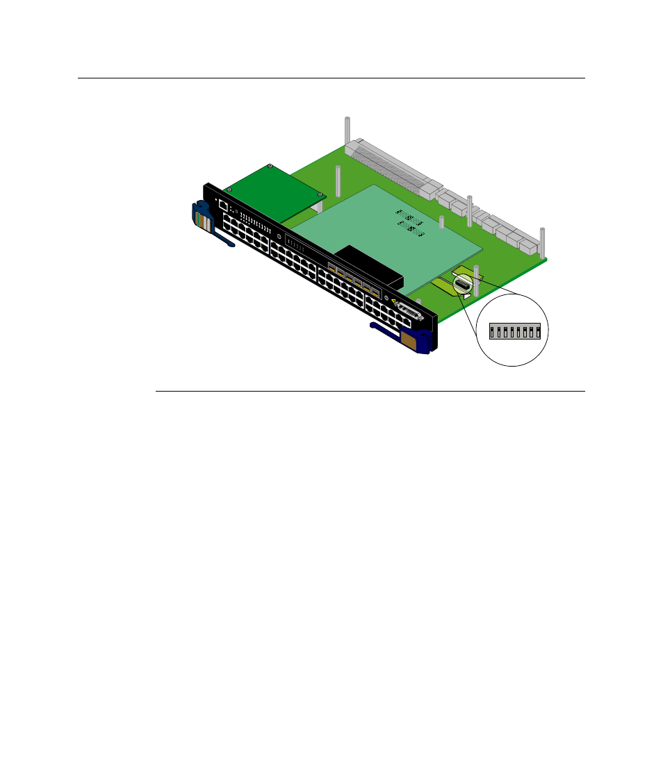
Figure B-1 Mode Switch Location (4H4285-49 shown without safety cover)
Memory Locations and Replacement Procedures
If the Dual in Line Memory Module (DIMM) or DRAM Single In‐line Memory Module
(SIMM) (FLASH memory) needs to be replaced, the following sections describe how to
access, locate, and replace these memory modules. If you have questions concerning the
replacement of either memory module, refer to
“Getting Help”
on page xviii for details
on how to contact Enterasys Networks.
shows the DIMM and DRAM SIMM locations on the main PC board.
1 Mode switch pack (4H4285-49 shown without safety cover)
1X
G R
O U
P
1
G R
O U
P
2
11X
13X
23X
OFFLINE/ RESET
COM
CPU
M
G
M
T
GR
OUP
SELECT
GR
OUP
1
2
3
4
5
6
7
8
9
10
11
12
POE
12
X
14X
24X
G R
O U
P
3
25X
35X
26X
36X
G R
O U
P
4
37X
47X
38X
48X
1
2
3
4
48V
---
20A
MAX
OPTIONAL
PO
WER INPUT
4H
42
85
-4
9
FAST ENET
DFE
1 2 3 4 5 6 7 8
ON
À
1
2
3
4
5
6
1
2
3
4
5
6
7G-6MGBIC-A