Enterasys Networks Enterasys Gold Distributed Forwarding Engine 4H4285-49 User Manual
Page 78
Gaining Access to Memory Modules
B-8 Mode Switch Settings and Option Installations
2.
Remove the two screws fastening the NEM to the DFE‐Gold module front panel and
remove the standoff fastening the NEM to the main board. Save the two screws and
standoff for later use to reinstall the NEM.
3.
Lift and remove the NEM off the two main PC board connectors. Now you have
access to the DRAM SIMM. To replace the DRAM SIMM, proceed to “
.
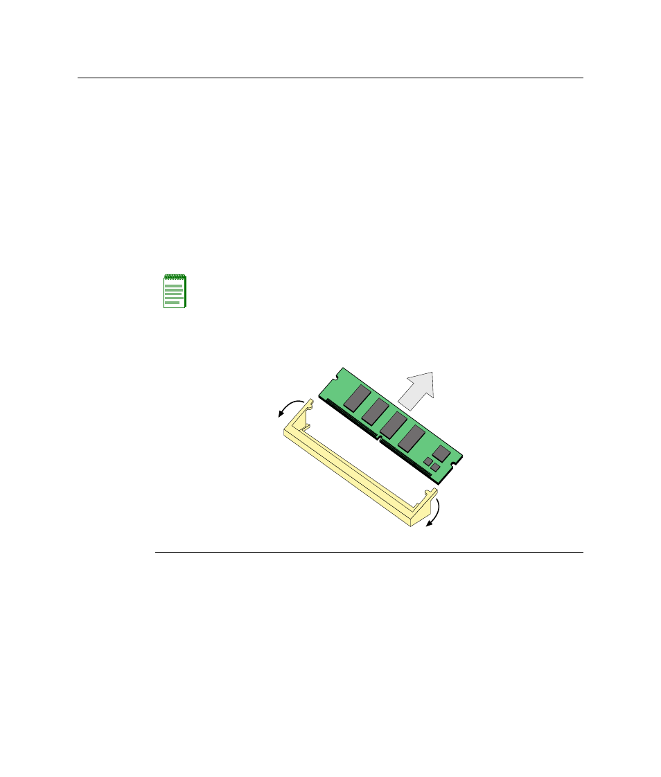
Removing the DRAM SIMM
To remove the DRAM SIMM, refer to
1.
Refer to
. Push the connector arms away from the DRAM SIMM to release it
from the connector.
2.
Remove the DRAM SIMM from the connector.
Figure B-5 Removing the Existing DRAM SIMM
Note: The ejector arms on this connector are not spring-loaded, so they will remain in the
open position until manually closed.
1 Connector arms
2 Memory module
3 Connector
В
А
А
Б