Figure 3‐1, Ad c b – Enterasys Networks Enterasys Gold Distributed Forwarding Engine 4H4285-49 User Manual
Page 32
DFE Module Placement and Installation Rules
3-4 Installation
To ensure proper operation of the system, consider the following examples and rules for
module placement in either chassis.
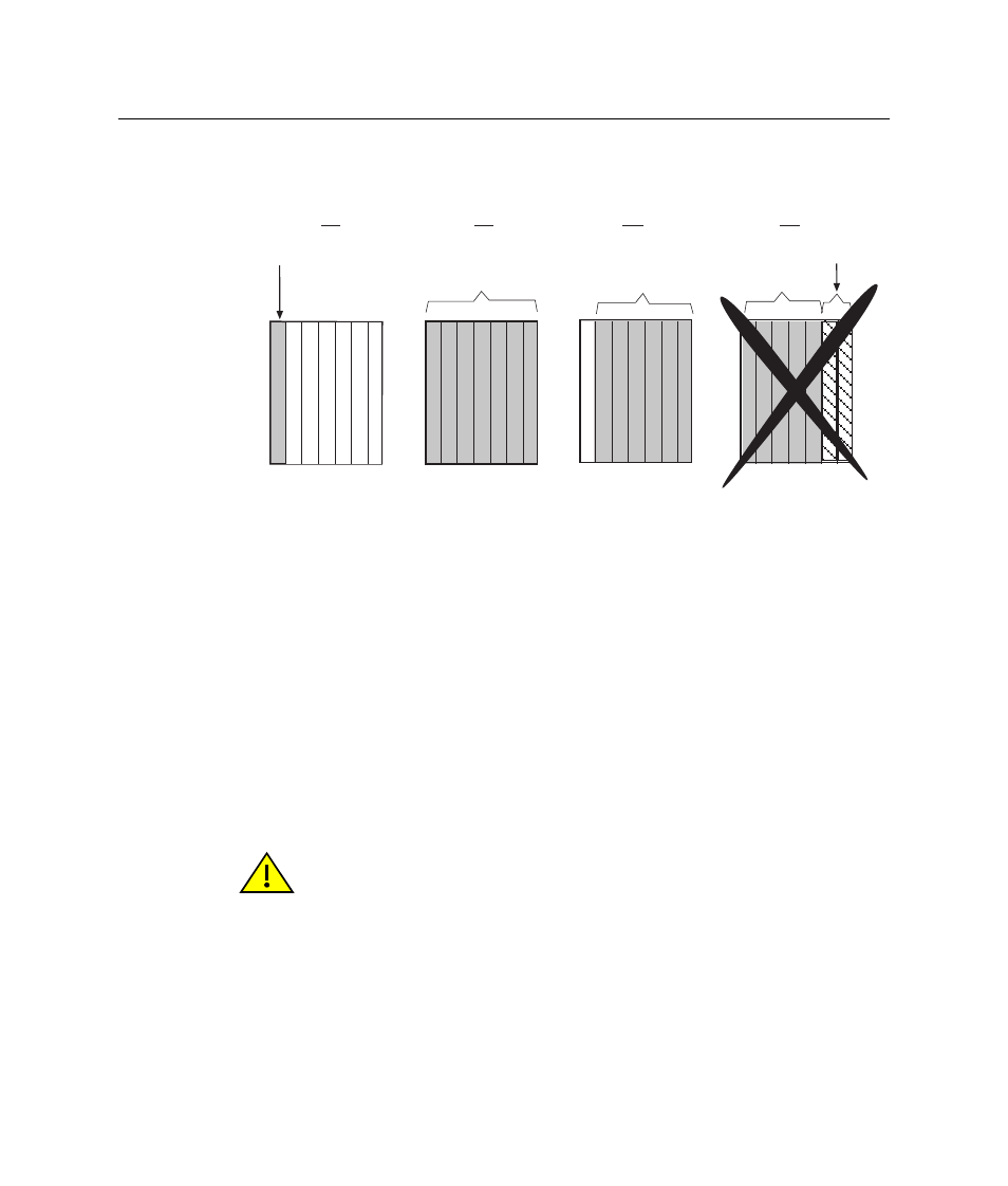
Example 1 (
Shows one module installed in the chassis. If the chassis is populated with only one
4xxxxx, it must be installed in slot 1.
Rule: If only one 4xxxxx is installed in the chassis, it must be in slot 1. Always install a
4xxxxx in slot 1 of the chassis.
Example 2 (
Shows the chassis fully populated with 4xxxxx modules. By default, the chassis system
can continue to operate after losing operation of all modules except the module in slot 1.
(The loss of operation can be due to module reset, removal, or failure.) However, with the
redundancy key installed, the system will remain operational provided that there is an
operating module in slot 1 or 2.
Figure 3-1 Examples, Slot Numbers/Module Placement in Matrix E7 or N7
Caution: When installing a module into slot 1 of a non-operating chassis, it is strongly
recommended that the module have the desired version of firmware. Installation of a
replacement module into slot 1 of a non-operating chassis requires reconfiguration of the
system settings.
Precaución: Para instalar un módulo en la ranura 1 del chasis apagado, lo mejor es que
el módulo corresponda a la versión de firmware solicitada. Para instalar un módulo de
reemplazo en la ranura 1 del chasis apagado será necesario reconfigurar el sistema.
4XXXXX
1 2 3 4 5 6 7
4XXXXX
7XXXXX
1 2 3 4 5 6 7
4XXXXX
1 2 3 4 5 6 7
1 2 3 4 5 6 7
4XXXXX
A
D
C
B