Termination of tp cable, Termination of tp cable -16, Installation and operation, cont’d – Extron electronic TP Receivers User Manual
Page 28: Tp receivers • installation and operation, Figure 2-9 — power connector wiring, Figure 2-10 — tp cable termination
TP Receivers • Installation and Operation
Installation and Operation, cont’d
2-16
TP R BNC A —
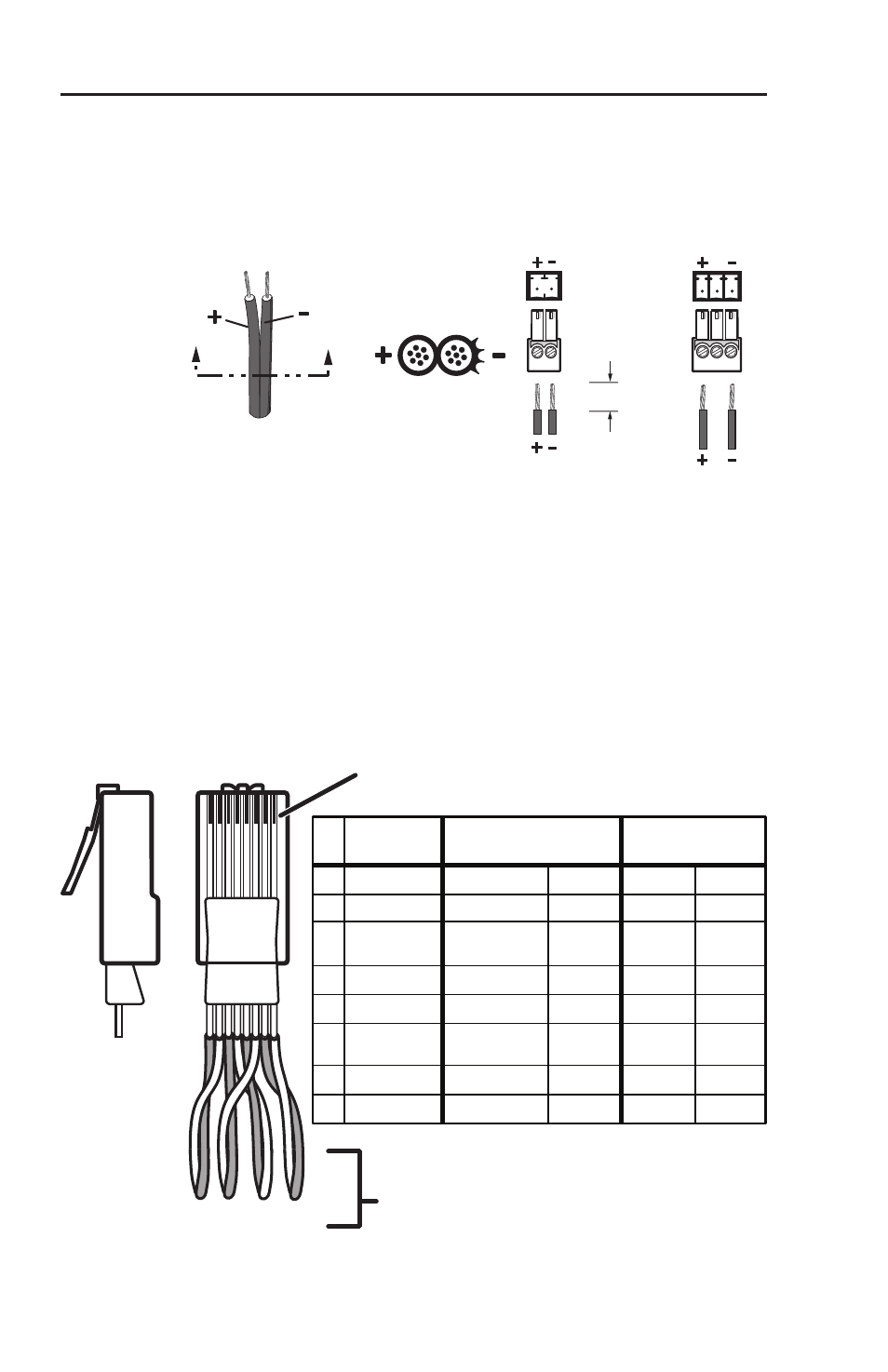
Wire the external 15 V power supply into
this 3-pole captive screw connector (figure 2-9) and
plug the connector into the receiver. The power
supply is included with the unit.
SECTION A–A
Power Supply
Output
Cord
Ridges
Smooth
A
A
TP R 15HD A
3/16”
(5 mm)
Max.
TP R BNC A
N/C
N/C
Figure 2-9 — Power connector wiring
TP R 15HD A —
Wire the external 15 V power supply
into this 2-pole captive screw connector (figure 2-9)
and plug the connector into the receiver. The power
supply is included with the unit.
Termination of TP cable
Figure 2-10 details the termination of TP cables in accordance
with the TIA/EIA T 568A wiring standards.
Clip Down
Side
1
1&2
3&6 4&5
7&8
2345678
12345678
Pin Wire color
RGB video and audio
AV Video and audio
Signal
Level
Signal
Level
1 White-green
Red/V. sync+
±0.35 V
Video+
+0.35 V
2 Green
Red/V. sync-
±0.35 V
Video-
-0.35 V
3 White-orange Audio &
power
+15 V with
±0.5 V
+15 V
4 Blue
Green+
+0.35 V
Reserved None
5 White-blue
Green-
-0.35 V
Reserved None
6 Orange
Audio &
power
Audio+* &
power+
Audio-* &
power-
±0.5 V
0 V
7 White-brown Blue/H. sync+
±0.35 V
Reserved None
8 Brown
* Audio can be jumpered to wire pair 7 and 8.
See Audio jumpers
in this chapter.
Blue/H. sync-
±0.35 V
Reserved None
RJ-45
connector
Twisted
Pairs
Figure 2-10 — TP cable termination