Installation and operation, cont’d, Video jumpers, Tp receivers • installation and operation – Extron electronic TP Receivers User Manual
Page 16: Figure 2-1 — video jumper configuration, Component, s-video, composite j3, Tp r bnc av
TP Receivers • Installation and Operation
Installation and Operation, cont’d
2-4
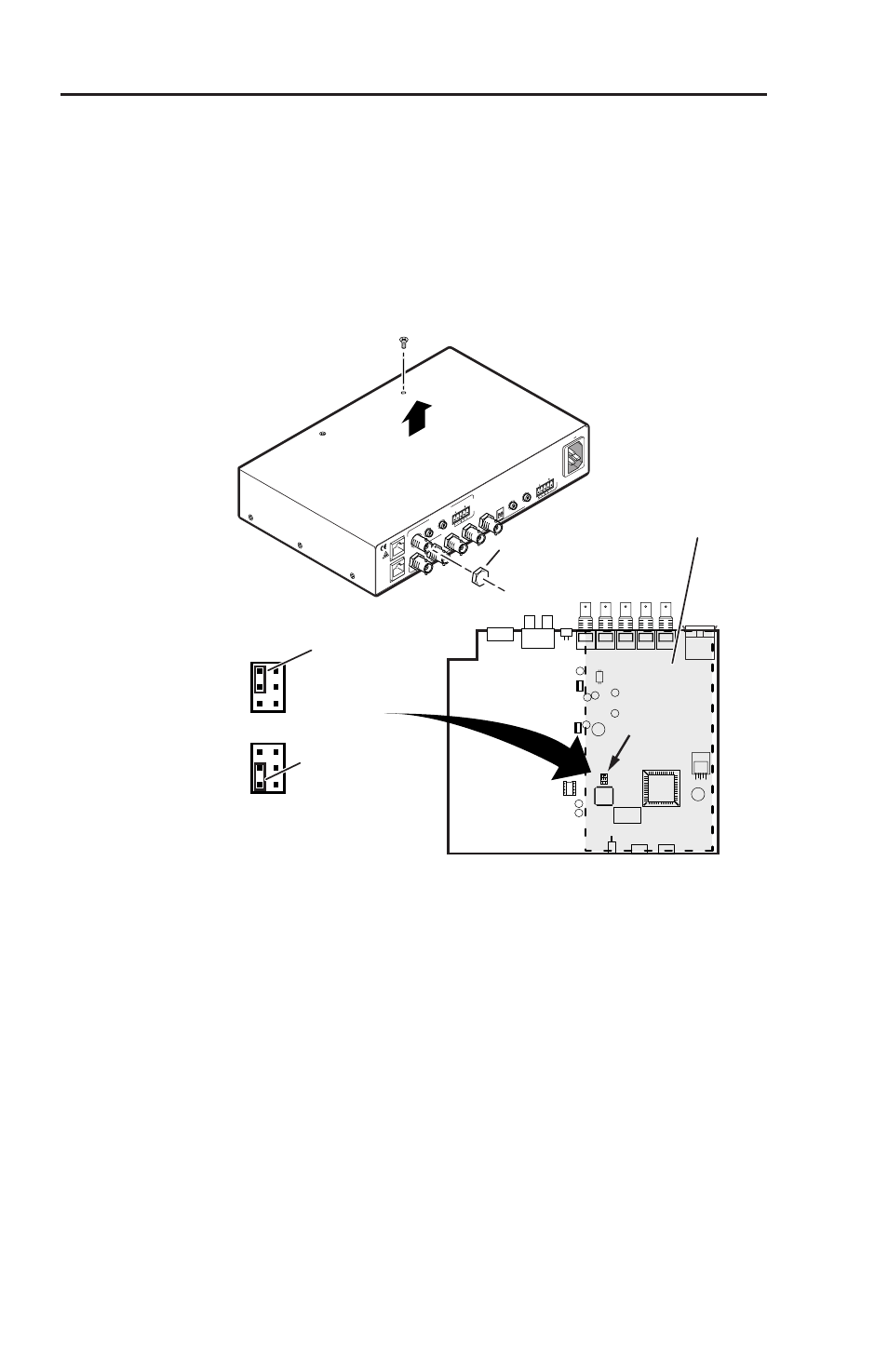
Video jumpers
The TP R BNC A and TP R BNC AV receivers can be configured
to receive component video, S-video, or composite video.
N
The receivers are factory configured for RGB video. To
receive any other type of video, reconfigure the jumpers.
1
.
Remove the three screws on each side and the two screws
on top of the cover (figure 2-1).
RGB
Bottom PC board (inside case)
TP R BNC A and TP R BNC AV
For
TP R BNC AV
Remove Top PC board
J3
1
2
3
J3
U25
Component,
S-video,
Composite
J3
1
2
3
J3
RG
B O
UT
PU
T
RG
B I
NP
UT
A-V
IN
PU
T
A-V
OU
TP
UT
AU
DIO
R
VID
EO
G
B
H/H
V
V
A
AU
DIO
L
R
B
A
L
R
B
IS
OG C
SY
NC
50/
60
Hz
100
-24
0V
1.3
A
Lift Cover
Straight Up
TP R BNC AV
Remove 8
Screws
Remove 5 (
TP R BNC A)
or 6 (
TP R BNC AV)
BNC Hex Nuts
Figure 2-1 — Video jumper configuration
2
.
Using an Extron BNC extraction tool (part #100-096-01) or a
14 mm, deep well socket with thin walls, remove the five or
six hex nuts securing the BNC connectors to the rear panel.
3
.
Slide the cover to the rear until the cover clears the BNC
connectors and then lift the cover off.
4
.
TP R BNC AV only
: Remove the four screws securing the
video board to the RGB board and lift the video board out
of the way.