Installation and operation, cont’d, Tp receivers • installation and operation, Figure 2-2 — audio jumper configuration – Extron electronic TP Receivers User Manual
Page 18
TP Receivers • Installation and Operation
Installation and Operation, cont’d
2-6
1
.
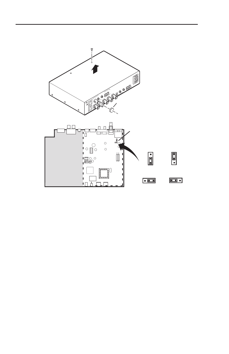
Remove three screws on each side and one or two screws on
top of the cover (figure 2-2).
RGB OUTPUT
RGB INPUT
A-V INPUT
A-V OUTPUT
AUDIO
R
VIDEO
G
B
H/HV
V
A
AUDIO
L
R
B
A
L
R
B
ISOG
C SYNC
50/60 Hz
100-240V 1.3A
Lift Cover
Straight Up
TP R BNC AV
Remove 8
Screws
Remove 5 (
TP R BNC A)
or 6 (
TP R BNC AV)
BNC Hex Nuts
J10
J11
J11
J10
AV board in TPR BNC AV
Wire Pair
3&6*
Wire Pair
7&8
Wire Pair
3&6*
* TPX Compatible
Wire Pair
7&8
1
1
1
1
Figure 2-2 — Audio jumper configuration
2
.
Using an Extron BNC extraction tool (part #100-096-01) or a
14 mm, deep well socket with thin walls, remove the five or
six hex nuts securing the BNC connectors to the rear panel.
3
.
Slide the cover to the rear until the cover clears the BNC
connectors, then lift the cover off.
4
.
Locate J10 and J11 on the composite video printed circuit
board. See figure 2-2.
a
.
For compatibility with redesigned (modified)
receivers and the TPX 88 A
, ensure that pin 1 is
jumpered to pin 2 on both jumper locations.
b
.
For compatibility with older (unmodified) receivers
,
ensure that pin 2 is jumpered to pin 3 on both jumper
locations.
5
.
Replace the cover, and reinstall the screws and BNC
connector hex nuts.