Installation and operation, cont’d, Installing the mounting bracket with clips, Installing the mounting bracket with screws – Extron Electronics RGB 500_Dual User Manual
Page 8: Setting bottom and top panel switches
RGB 500 Series • Installation and Operation
RGB 500 Series • Installation and Operation
Installation and Operation, cont’d
injury to yourself or the cables during installation.
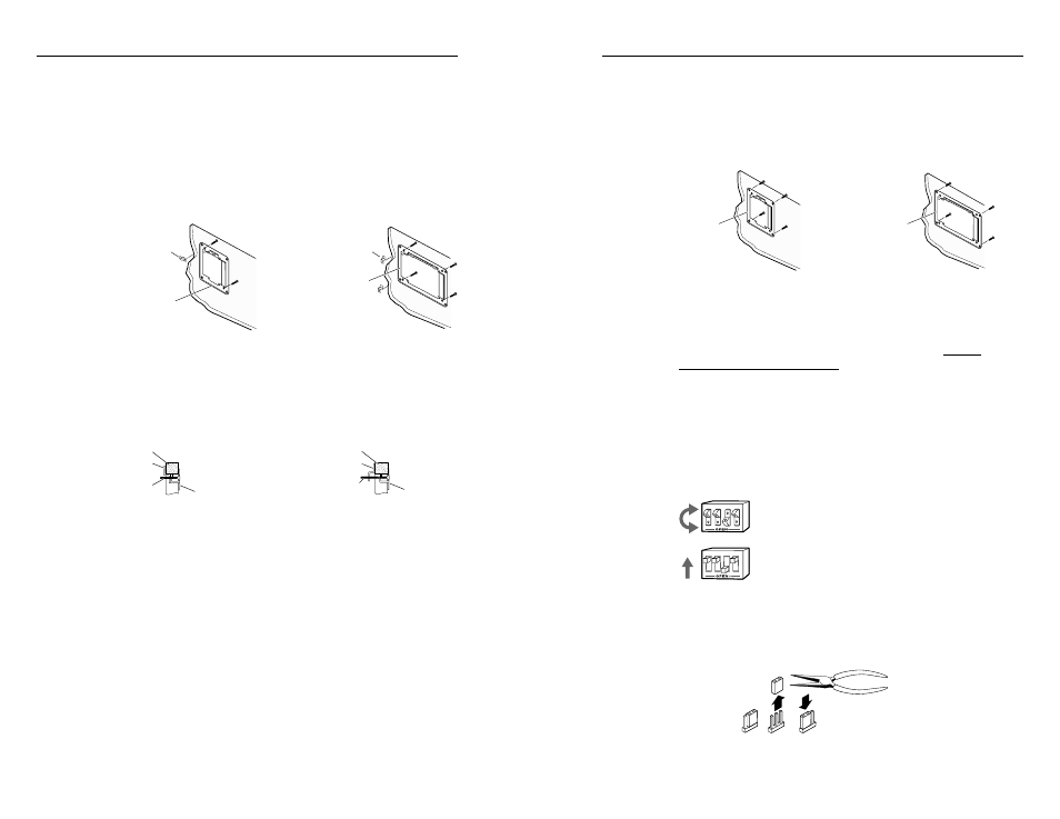
Installing the mounting bracket with clips
1.
Place 1¼” (3.18 cm) long or ¾“ (1.9 cm), #6-32 machine
screws (provided) through the holes in each corner of the
mounting bracket. Use the shortest screw required.
Loosely fasten (using 2-3 turns) a mounting backing clip
on the end of each screw.
2.
Insert the mounting bracket into the opening in the wall.
Installing the mounting bracket with backing clips
3.
Rotate each clip so the tab will be behind the plywood,
wallboard/sheet rock or other surface to hold the bracket
snugly in place when the screw is tightened. See Detail A
and Detail B.
Detail A
0.75" #6-32 Screw
Backing Clip
Backing Clip
Wall Material
Wall Material
Mounting Bracket
Mounting Bracket
Detail B
1.25" #6-32 Screw
Backing clip orientations
4.
Use a Phillips screwdriver to hand tighten the screws to
fasten the mounting bracket in place.
Installing the mounting bracket with screws
Use this installation method if the installation surface is a sturdy,
dense material such as sheet metal, plywood, or hard wood.
1.
Insert the mounting bracket into the opening in the wall
and hold it firmly in place.
2.
Mark the locations of the outermost/corner bracket holes
on the installation surface.
3.
If desired, remove the mounting bracket and drill ¼” deep
pilot holes (half the width of the shaft of the screw) at the
marked locations.
2-5
2-5
Mounting Bracket
Mounting Bracket
Backing Clip can
be in either orientation.
See Detail A or Detail B.
Backing Clip can
be in either orientation.
See Detail A or Detail B.
2-4
2-4
4.
Insert the bracket back into the hole.
5.
Use four ½” (1.3 cm) long, #6 flat headed wood screws
(provided) or self-tapping sheet metal screws to fasten the
bracket directly onto wood or metal, respectively. Hand
tighten the screws. See the illustration below.
Installing the mounting bracket with screws
Setting bottom and top panel switches
Because the top and bottom panels on all models will be
inaccessible after installation
, the DIP and jumper switches
must be set before the interface is installed into the wall,
furniture or raceway. Use the switch explanations to help you
configure these switches.
Set the DIP switches to either On (closed) or Off (open) to select
the desired function as described in the features section.
The DIP switches may be either the rocking type or the sliding
type.
To set rocking-type DIP switches, use a small
screwdriver to depress the appropriate end of
the switch.
To set the sliding type of DIP switches, use a
small screwdriver to slide (push) the switch to
the desired position (On/closed or Off/open).
To configure jumper switches, use a needlenosed plier to reach
through the openings in the enclosure and pull the jumper
shunt out/off the pins, then place the jumper on the appropriate
pins, as shown below.
Changing jumper settings
3
4
1
2
3
4
1
2
Mounting Bracket
Mounting Bracket