Installation and operation, cont’d – Extron Electronics RGB 500_Dual User Manual
Page 10
RGB 500 Series • Installation and Operation
RGB 500 Series • Installation and Operation
Installation and Operation, cont’d
2-9
2-8
Polarity is not important: the positive or negative wire
may be connected to either of the outer poles.
5
Bottom panel DIP switches —
These four DIP switches,
numbered 1 to 4 from left to right, control the sync on green,
serration pulse, DDSP and composite sync output options.
1 — SOG (sync on green)
ON — When this switch is set to On, (sync on green), the
interface will output sync on green.
OFF — When the SOG feature is set to Off, the interface
will output either separate horizontal and vertical
sync signals (on the H/HV and V connectors) or a
composite sync signal (on the H/HV connector),
depending on how DIP switch 4 is set.
2 — DDSP™ (Digital Display Sync Processing
™
)
ON — When this switch is set to On, the interface uses
Digital Display Sync Processing instead of
Advanced Digital Sync Processing
™
. Use this
option if the image still doesn’t display properly
after other options (changes to sync width,
serration pulses and video termination) have been
explored.
DDSP will disable horizontal shift control.
OFF — When this switch is set to Off, the interface uses
ADSP
™
, Advanced Digital Sync Processing
™
.
3 — SERR (serration pulse)
Many display devices, including LCD and DLP projectors
and plasma displays, must not have serration pulses in the
vertical sync signal in order to display properly. Flagging
or bending at the top of the video image is a sign that the
serration pulses should be removed.
ON — When this switch is set to On, serration pulses will
be output.
OFF — When this switch is set to Off, serration pulses will
not be output.
4 — Composite sync
ON — When this switch is set to On, a composite sync
signal (H and V combined) will be output on the
connector labeled “H/HV”.
OFF — When this switch is set to Off, horizontal sync will
be output on the connector labeled “H/HV”, and
vertical sync will be output on the “V” connector.
6
Blue (B) output connector —
BNC female connector for blue
video output.
7
Green (G) output connector —
BNC female connector for green
video output.
8
Red (R) output connector —
BNC female connector for red
video output.
9
Horizontal (H) or composite sync (HV) output connector (H/
HV) —
BNC female connector for either separate horizontal sync
or composite sync output.
10
Vertical (V) sync output connector —
BNC female connector for
separate vertical sync output.
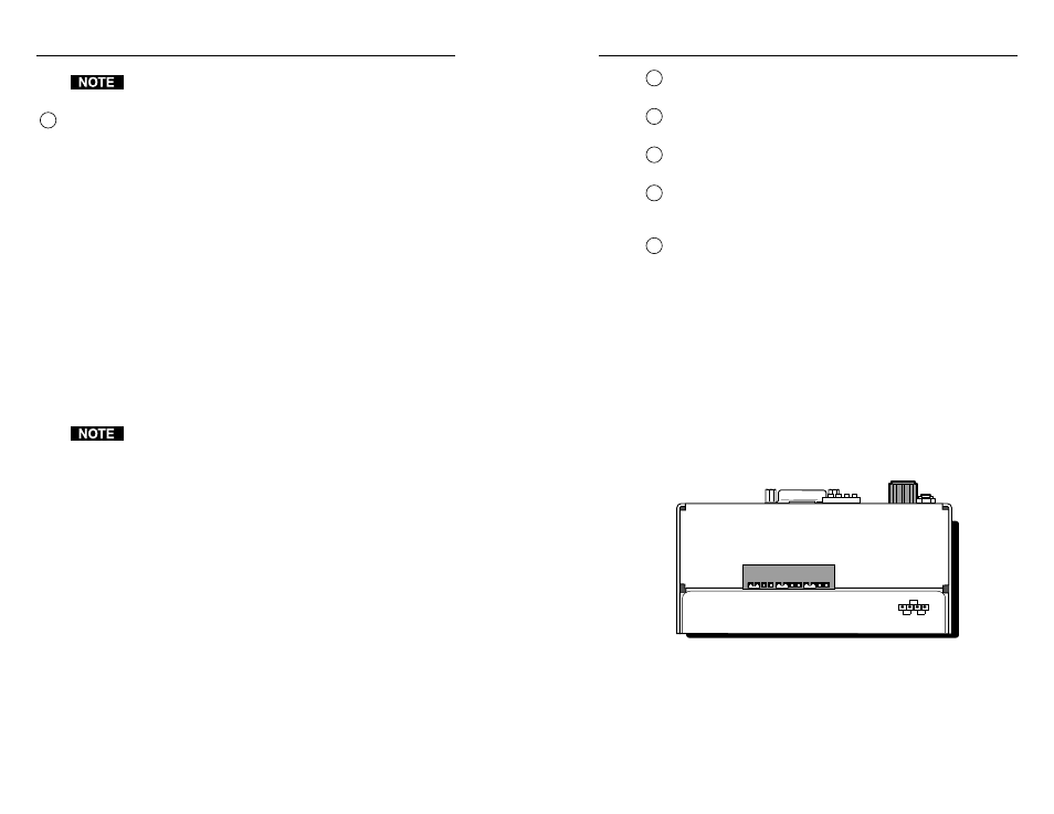
Top panel jumper switches
Video signals passing through long cable runs (over 125 feet)
can decrease in strength, creating signal loss. The longer the
cable, the higher the video level and the greater the peaking
that will be needed to compensate for the loss.
The red, green and blue gain/peaking adjustment jumper
switches are located on the top of the RGB 500 Series interfaces.
You will need needlenosed pliers to reach and move the
jumpers. Select the setting that yields the best image display.
Use the diagram on the product label, shown in the illustration,
as a guide to setting the output gain/peaking for each color.
BLUE
GREEN RED
Unity
50% 100%
33-511-01 Rev. A 07 99
Gain/Peaking Adjustment Jumpers
RGB 500 Series Interface
Top view of an RGB 500 Series interface
• Use the left two pins to increase the output signal and add 50%
of the maximum peaking to the signal.
• Use the middle two pins for unity output (0.7 volts,
no peaking).