Switch configured for vlans – Enterasys Networks 6H2xx User Manual
Page 395
Example 1, Single Switch Operation
VLAN Operation and Network Applications
13-23
4. The ports 1 through 6 are configured as follows using the VLAN Port Configuration screen:
•
Ports 1, 2, and 3 are set as follows:
PVID: 2
Acceptable Frame Types: ADMIT ALL FRAMES
Ingress Filtering: ENABLED
GVRP Status: DISABLED
•
Ports 4, 5, and 6 are set as follows:
PVID: 3
Acceptable Frame Types: ADMIT ALL FRAMES
Ingress Filtering: ENABLED
GVRP Status: DISABLED
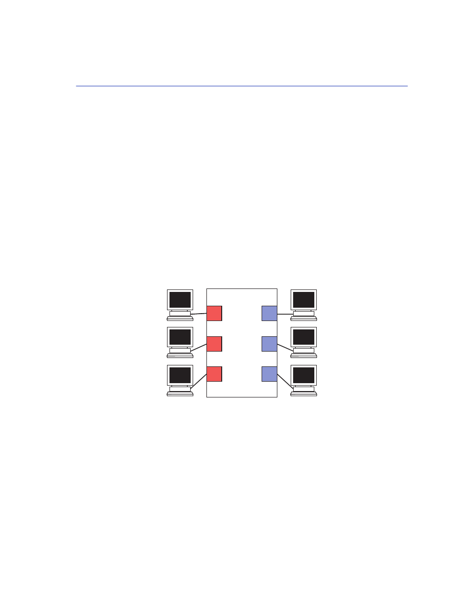
5. The VLANs and ports are now configured and enabled.
shows the resulting VLAN
assignment to each port.
Figure 13-11
Switch Configured for VLANs
The switch will now classify each frame received as belonging to either the Red or Blue VLANs.
Traffic from one VLAN will not be forwarded to the members of the other VLAN, and all frames
transmitted by the switch will be normal, untagged Ethernet frames.
3
6
2
4
5
B2
B1
B3
R1
R2
R2
802.1Q Switch
VLAN ID 002
VLAN ID 003
VLAN ID 002
VLAN ID 003
VLAN ID 002
VLAN ID 003
1
30691_68