Chapter 3, Motherboard information – Lanner FW-8893C User Manual
Page 20
15
Motherboard Information
Chapter 3
Network Application Platforms
Note:
The management port on the front panel
1.
will not pass through when the IPMI card is
present (board reference NO. OPMA1); The
management port and IPMI share the same
output port (the LAN1 port on the front panel).
Use the jumper J110 to switch between these
two signals.
A simple workaround: To have both VGA and
2.
Management function(non- IPMI compliant)
connections, take out the jumper block on
J110.
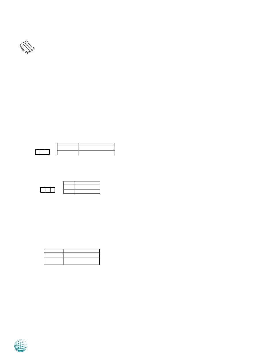
Reset Function Selection (J91): A reset switch to
switch between hardware and software reset function for
the front panel reset button. A hardware reset function
will reset the whole system while a software reset function
will reset the designated software to its default value.
Clear CMOS Jumper(J29): Use this jumper to reset
the BIOS setting to its factory default.
IPMI and Management Port Switch (J110): A
switch to switch the output signal between management
and OPMA1 since they share the same access port
(the management port on the front panel). To let the
management signal pass through instead of the OPMA
signal (refer to jumper OPMA1), take out this jumper. In
this way, you could have both VGA and Management
connections (non-IPMI).
Pin No.
Description
1-2
Hardware Reset
2-3
Software Reset
3 2 1
Pin No.
Description
1-2 Normal (default)
2-3
Clear CMOS
1 2 3
Pin No.
Description
Short1-2
IPMI signal
Open
Management signal
pass through