Chapter 3, Motherboard information – Lanner FW-8893C User Manual
Page 19
14
Motherboard Information
Chapter 3
Network Application Platforms
CPU Socket NO.1 and CPU Socket NO. 2: When
using only one CPU, install the CPU on the socket NO.1 or
the system will not function.
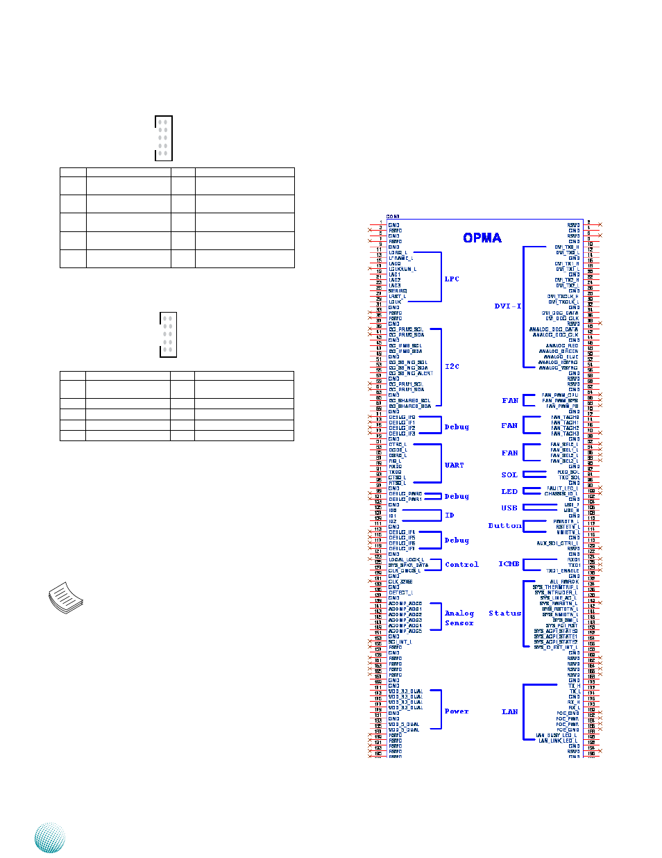
OPMA1: OPMA Connector. The OPMA connector
is for connecting the OPMA card. When the OPMA card
is connected, the management port will comply with
the Intelligent Platform Management Interface (IPMI)
standard.
COMB4: COM PORT Connector
COMB5: Bypass function programmer
DIMM Sockets:
Since the system is capable of Quad Channel
configuration, some installation guidelines have to be
followed to enable Quad Channel mode. To insert 4 DIMMs
on the system, insert DIMMS into the 4 black slots with
black latches nearest to the designated CPU socket (CPU
socket No1 or No2). And then use slots with white latches
if more slots are required.
Note:
To activate Dual Channel instead of Quad
1.
Channel in the system, populate any 2 slots
with black latches nearest to the designated
CPU socket (CPU socket No1 or No2). And then
use slot(s) with white latch that belongs to the
same channel as the populated slots for any
additional DIMMs.
Starting from the board edge (same for both
2.
CPU socket No1 and No2), one pair of black
and white-latched slots is configured as one
channel.
2
4
6
8
10
1
3
5
7
9
Pin No.
Description
Pin No.
Description
1
Data Carrier Detect
(DCDB #)
6
Clear To Send
(CTSB #)
2
Data Set Ready
(DSRB #)
7
Data Terminal Ready
(DTRB #)
3
Receive Data
(RXDB)
8
Ring Indicator
(RIB #)
4
Request To Send
(RTSB #)
9
Ground
5
Transmit Data
(TXDB)
10
KEY
2
4
6
8
10
1
3
5
7
9
Pin No.
Description
Pin No.
Description
1
NC
6
NXP_CTS_N
2
NC
7
NC
3
NXP_RXD
8
NC
4
NXP_RTS_N
9
GND
5
NXP_TXD
10
P3V3_SB