Jordan Valve Mark ED & ET Series (8) Globe Style Control Valve User Manual
Page 4
-4-
Replacing TFE V-Ring Packing
1.
After the stem and valve plug have been
detached from the bonnet, the following parts
can be removed:
1.1.
Packing nuts
1.2.
Packing flange
1.3.
Wiper ring
1.4.
Packing follower
2.
The old packing can be removed by one of two
methods:
2.1.
Remove the packing by pushing it out
using a rod inserted through bottom of
the
bonnet.
2.2.
Use a packing hook to remove the
packing. Note: To avoid damaging the
packing box walls use caution.
3.
Clean the packing box bore, and all metal
parts. Complete all required maintenance.
4.
Slide the valve plug into the cage already in
the valve body, install the load ring on the
cage, and use a new bonnet gasket. Mount
the bonnet to the valve body.
5.
Complete the installation of the packing as il-
lustrated in Figure 3.
Note: Extra caution should be taken not to damage
the packing during the installation process.
6.
Replace the packing flange (Key 27); tighten
the packing flange nuts (Key 29) until shoulder
of packing follower (Key 30) is approximately
5/8” from the top of the bonnet. If leakage is
detected around the packing follower, tighten
the packing flange nuts until leakage stops.
7.
For graphite packing, tighten the packing
flange nuts to the maximum torque value in
Table 3. Then back off the nuts and retighten
them to the minimum torque value in Table 3.
8.
For other Packing Types, in small equal incre-
ments tighten the flange nuts until one of the
nuts reach the minimum torque shown in Table
3. Then tighten the other nut until the packing
flange is level.
9.
Mount the actuator and set the stem connector
to the required travel. Refer to “Making Up the
Stem Connection” procedure.
Lapping Metal Seats
In any valve body, a certain amount of leakage should
be expected with metal-to-metal seating. However, if
the leakage becomes excessive, lapping can enhance
the condition of the seating surfaces of the valve plug
and seat ring.
Deep nicks in the seating surfaces should be removed
by machining rather than lapping. There are many lap-
ping compounds available commercially. Be sure to
use one of high quality.
Apply lapping compound to bottom of plug. In order
to position the cage and seat ring properly and to help
align the valve plug with the seat ring, bolt the bon-
net to the body with gaskets (the old gaskets can be
used) in place during the lapping procedure. A simple
handle can be made from a piece of metal secured to
the valve stem with nuts.
Rotate the handle in opposite directions to lap the seat-
ing surfaces. Once lapping is complete, disconnect
bonnet, clean the seating surfaces, reassemble, and
then test for shutoff. If leakage is still excessive, repeat
lapping procedure.
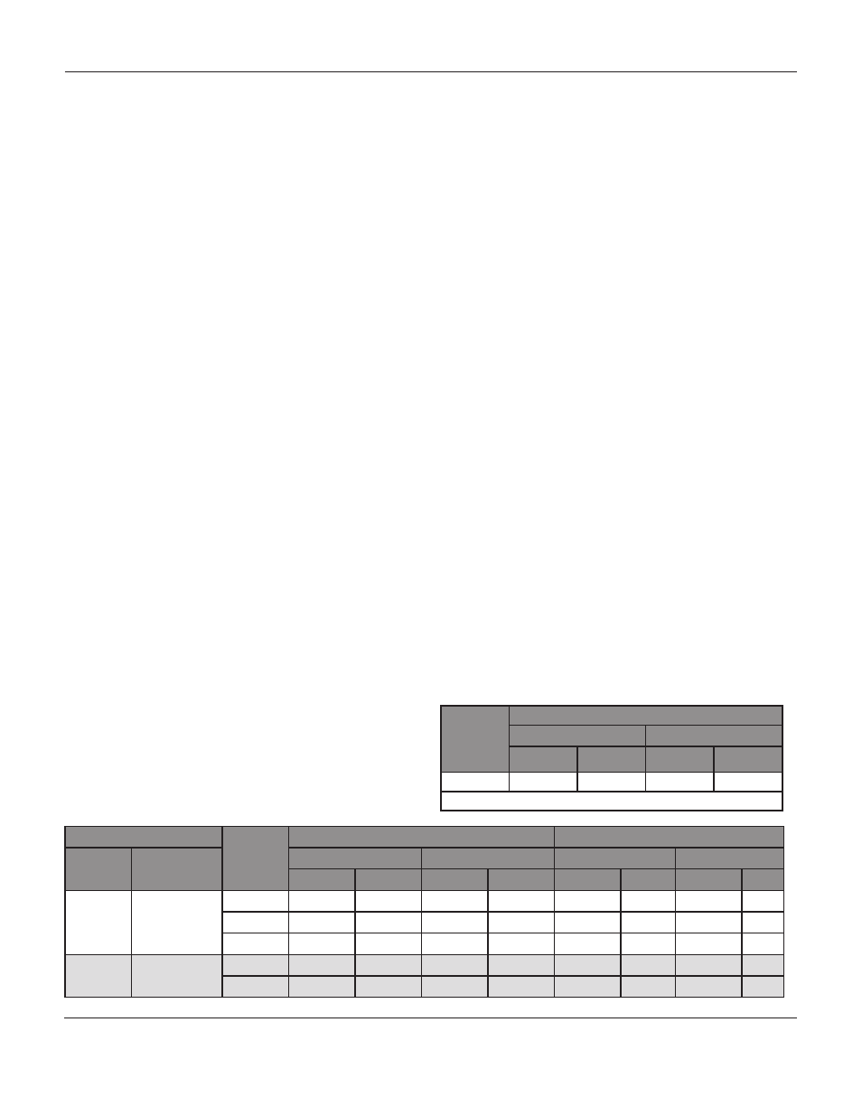
Valve Size
Bolt Torques
SA 193-B7, B8M
a
SA-193-B8M
b
N•m
Lbf•Ft
N•m
Lbf•Ft
8
746
550
529
390
a- Strain Hardened; b- Annealed
Valve Stem Diameter
ANSI
Rating
PTFE Type Packing
Graphite Type Packing
Inches
Mm
Min. Torque
Max. Torque
Min. Torque
Max. Torque
Lbf•in
N•m
Lbf•in
N•m
Lbf•in
N•m
Lbf•in
N•m
3/4
19.1
150
47
5
70
8
99
11
149
17
300
64
7
95
11
133
15
199
23
600
87
10
131
15
182
21
274
31
1
25.4
300
108
12
162
18
226
26
339
38
600
149
17
223
25
310
35
466
53
Table 3: Torque Values for Packing Flange Nuts
Table 2: Body to Bonnet Torque
M
ark
ED
anD
ET S
EriES
8-
inch
G
lobE
S
TylE
c
onTrol
V
alVES