Jordan Valve Mark ED & ET Series (8) Globe Style Control Valve User Manual
Page 3
-3-
Assembly Continued,
4.
Replace the seat ring gasket, and install the seat
ring. If using a composition seat (TFE),
assemble it by placing the TFE disc onto
the disc retainer and then sliding this assembly
over the disc seat.
5.
Place the cage onto the seat ring. Any rotational
orientation of the cage with respect to the valve
body is acceptable.
6.
To ensure a good seal, clean all sealing surfaces
and examine surfaces for nicks and scratches.
Place the bonnet gasket in position.
7.
Slide the valve plug assembly in the cage, and
then position the load ring on top of the cage.
8.
Place the bonnet on the body ensuring that the
pipe plug (or lubricator) is on the downstream
side of the body.
9.
Using good bolting practices, bolt the bonnet
to the body. Lubricate the studs and nuts us
ing good quality lubrication.
Tighten the bolts alternately.
Correct tightening of the bonnet bolts
accomplishes two objectives.
9.1.
To compress the bonnet gasket to form
a seal with the body joint.
9.2.
Bolt loads are transmitted to the cage
through the load ring, which creates a
sealing load for the seat ring gasket.
10.
Mount the actuator to the bonnet and make up
the stem connection. Refer to “Making Up the
Stem Connection” for proper procedure.
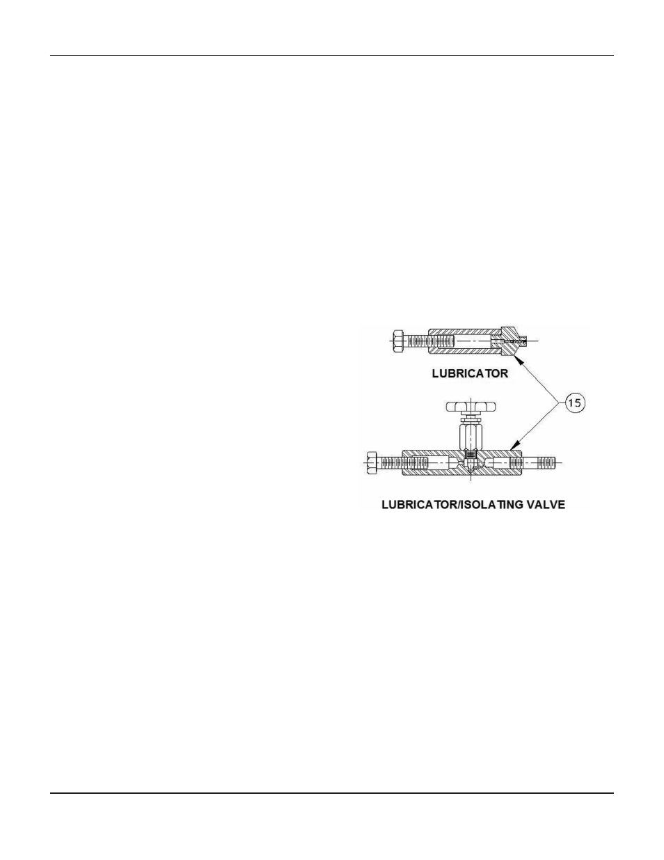
Packing Lubrication
The use of semi-metallic packing requires the use of a
lubricator or lubricator/isolating valve (Figure 2). The
lubricator or lubricator/isolating valve is mounted in
place of pipe plug (Figure 2, Key 15). For standard
service up to 450ºF, use Dow Corning lubricant or
equivalent. Do not lubricate packing used in oxygen
service.
Lubricator
-To add lubricant to the packing box, turn
the cap screw in a clockwise direction.
Lubricator/Isolating Valve
- Open the isolating valve,
turn the cap screw in a clockwise direction, and then
close the isolating valve.
Figure 2: Lubricator and Lubricator/
Isolating Valve
M
ark
ED
anD
ET S
EriES
8-
inch
G
lobE
S
TylE
c
onTrol
V
alVES