Gti units – Ericsson LBI-39076B User Manual
Page 11
DESCRIPTION
LBI-39076B
11
The Site Controller computer directs up to 16 levels of
toll call restrictions, up to 15 rotary hunt sequences, 8 de-
queuing priority levels, and inbound interconnect
enable/disable assignments, for each ID number. It also
accumulates interconnect call activity data for the System
Manager.
The standard ELI option consists of one or more GTI
units, one GTI Interface card, one set of two GTI
Configurator software diskettes, one set of two Site
Controller computer Personality PROMs, and the necessary
cables and hardware. The ELI option may also consist of an
optional Interconnect Accounting Manager (IAM) unit. The
GTI interface card is to be installed into one of the GTI units
making it the Master GTI.
The ELI option utilizes a distributed switching system
architecture that distributes the switching function between
the separate GTI units rather than concentrating it at a
centrally located telephone switch. Additionally, each GTI
unit receives its power from a separate repeater power
supply.
A typical ELI installation containing two GTI units, a
Master GTI, and an optional IAM is shown in
Figure 1. The function of each cable and bus
termination shown, is as follows (see parts list for part
numbers):
S - The serial data cables connect the Master GTI to the
Site Controller computer. (Two are used.)
P - The power cable connects the optional IAM to the
power supply of the associated repeater. (One is
used if an IAM is supplied.)
A/P - The audio/power cable connects a GTI or Master
GTI to a MASTR II/III repeater and its power
supply. (One is used for each GTI or Master GTI
assigned to a MASTR II/III repeater.)
PCM - The PCM/Data bus sections connect each GTI,
the Master GTI, and the optional IAM in a daisy-
chain. (Section lengths depend upon the position
of the units. The total number of bus sections is
one less than total number of units used.)
T - The termination for the PCM/Data bus terminates
the high channel end of the bus. (One is used.)
GTI UNITS
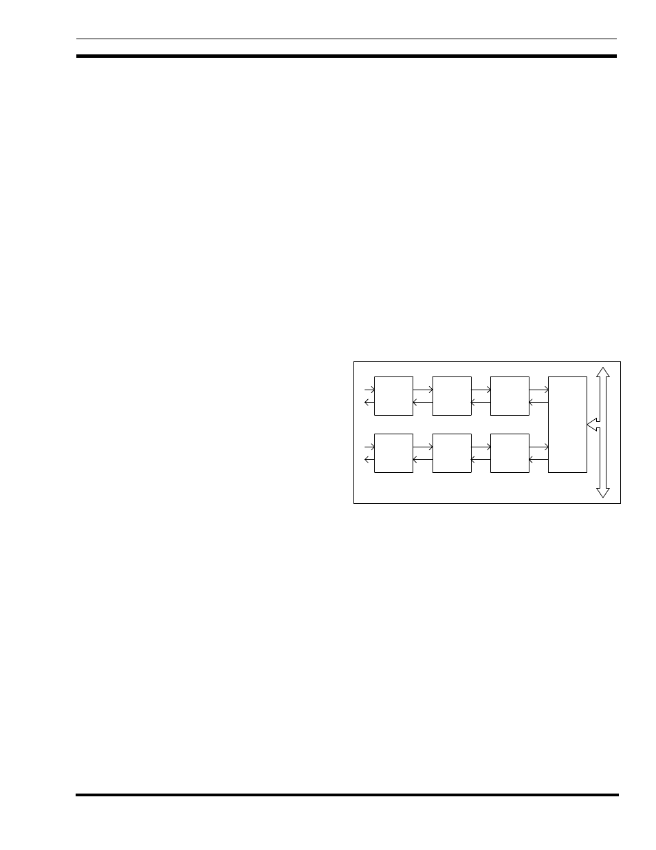
Each GTI (Global Telephone Interconnect) unit
contains both a radio channel interface and a telephone line
interface. For each interface, the GTI contains both analog-
to-digital and digital-to-analog converters, and a digital
signal processor. The relation of these circuits to the audio
paths is shown in
Figure 2.
The radio channel interface provides the following
functions:
•
Decodes DTMF from radio for radio-originated
call.
•
Sends ringback or busy tone to radio for radio-
originated call.
•
Sends ringing signal to radio for telephone-
originated call.
Telephone
Interface
Repeater
Interface
CODEC
Digital/Analog
Converter
Converter
Digital/Analog
CODEC
Digital
Signal
Processor
Digital
Signal
Processor
Driver
Bus
and
Receiver
PCM / Data Bus
Figure 2 - GTI Audio Paths
The telephone line interface provides the following
functions for telephone-originated calls:
•
Detects signaling from telephone line.
•
Applies signaling to seize telephone line.
•
Detects and decodes overdialed telephone number
digits from telephone line.
•
Sends voice prompts to telephone line.
•
Detects end-of-call signaling from telephone line.
•
Removes signaling to drop telephone line.