2 drive set-up, Rive, 2cn standoffs – Yaskawa GPD505 User Manual
Page 6: Mounting holes
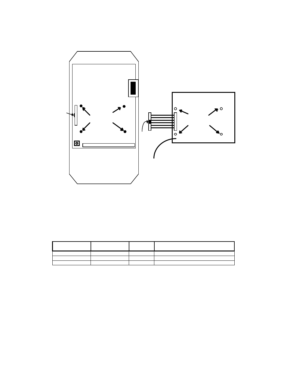
Step 5.
Route the green pigtail lead from the option board to the lower left corner of the control board
and connect it to screw terminal E(G).
2CN
Standoffs
GND
Mounting Holes
Cable
connector
E(G)
Locking Tab
Locking Tab
Figure 4. Option Card Positioning
2.2 Drive Set-up
The drive must be properly configured to communicate with the option card, as described below:
GPD505
Parameter
GPD506
Parameter
Setting Description
n106 n104
1
Address
(01)
n107
n105
2
Baud Rate (9600)
n108 n106
0
Parity
(None)
NOTE: Parameter n001 must be set to 3 to change these parameters. New settings will not take
affect until drive power is cycled.
If any of these settings are incorrect, “CALL” will blink on the digital operator, as will the RXD, TXD and
FAULT LEDs. This is an indication that the drive has not yet established communication with the option
card. Once the drive has properly exchanged messages with the option card, all blinking should stop.
TM4028
7/12/2001
6