Application overview, 1 analog input object summary, Nalog – Yaskawa GPD505 User Manual
Page 10: Nput, Bject, Ummary
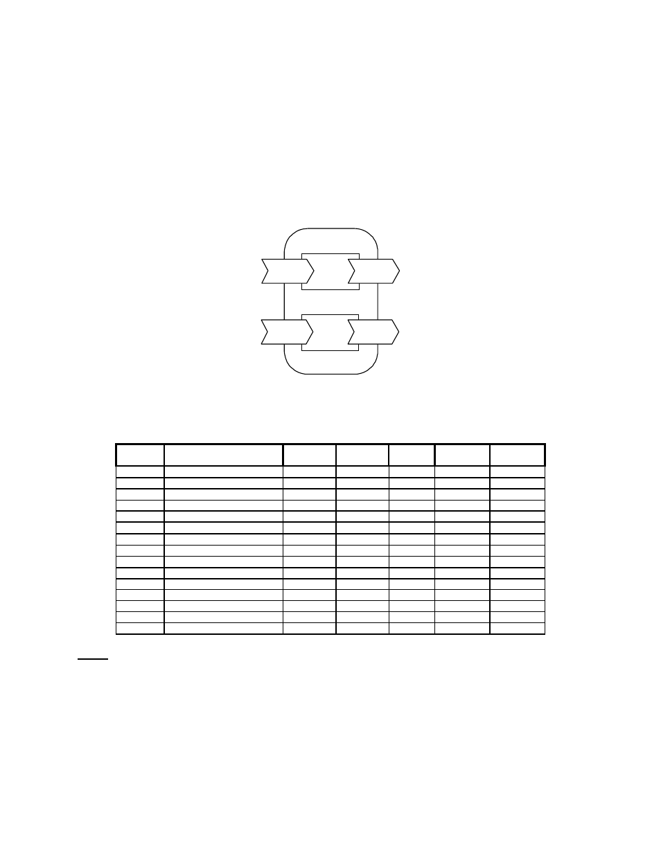
3. Application Overview
The drive is configured, controlled, and monitored by a comprehensive set of Analog and Binary objects, as
illustrated in Figure 6. Note the convention regarding inputs and outputs (i.e. Network Output = Drive Input,
Network Input = Drive Output).
This chapter summarizes the available objects by their type. Additional detail can be found in Section 4,
Standard Operation, where objects are grouped together by function.
NOTE: The Metasys
®
Change of State (COS) feature is fully supported by this application.
Binary
Objects
Analog
Objects
GPD506
Network
Outputs
Network
Outputs
Network
Inputs
Network
Inputs
Figure 6. Device Overview
3.1 Analog Input Object Summary
Object
ID
Object Name
GPD505
Monitor
GPD506
Monitor
Units Min Max
AI1 Speed
Reference U-01
U-01
Note 1
0
Note 1
AI2 Output
Speed U-02
U-02
Note 1
0
Note 1
AI3 Output
Current U-03
U-03
A 0
Note 2
AI4
Kilowatt Hour Meter
n/a
U-15
kWh
0
9999
AI5 Output
Power n/a
U-06
kW
0
9999
AI6 Drive
Temperature n/a
Note 3
°C
AI7 PID
Feedback n/a
U-13
Note 1
0
Note 1
AI8
AC Output Voltage
U-04
U-04
V
0
Note 2
AI9
DC Bus Voltage
U-05
U-05
V
0
Note 2
AI10 Fault
Code U-09
U-09
0
8191
AI11
Elapsed Timer – Hrs
U-11
U-11
Hr
0
9999
AI12
Elapsed Timer – 10K Hrs
U-12
U-12
10K Hr
0
27
AI13
Megawatt Hour Meter
n/a
U-16
mWh
0
9999
AI14
Drive Rated Current
Note 3
Note 3
A
Note 2
Note 2
AI15
Read Parameter Data
Note 4
Note 4
Note 4
Note 4
Note 4
Notes
1. Value dependent on setting of AO17, Operator Display Mode. Refer to Section 4.1.9.
2. Value dependent on drive capacity. Refer to appropriate Technical Manual.
3. Internal value only available via serial communication.
4. Value depends on the parameter being read (AO21).
TM4028
7/12/2001
10