Standard operation, 1 drive configuration, 1 accel/decel times – ao2, ao3 – Yaskawa GPD505 User Manual
Page 13: 2 pid configuration – ao4, ao5, ao9, 3 stall prevention – ao6, ao7, Standard, Operation, Rive, Onfiguration, 1 accel/decel
TM4028
7/12/2001
13
4. Standard Operation
The drive interface features 15 Analog Inputs, 23 Analog Outputs, 8 Binary Inputs and 10 Binary Outputs
for configuring, controlling, and monitoring its operation.
This chapter describes each aspect of operation, grouping the objects together by function. Objects are
summarized by type in Section 3, Application Overview.
4.1 Drive Configuration
This section describes the objects used to configure the drive. Refer to the appropriate Technical Manual
for additional information.
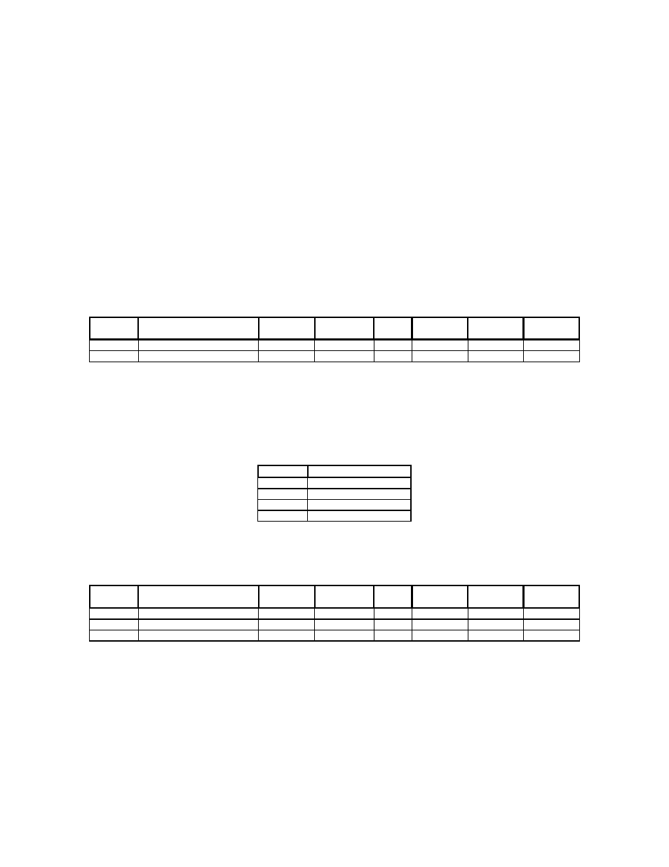
4.1.1 Accel/Decel Times – AO2, AO3
These analog outputs define the ramp rates for starting and stopping the motor, configuring the drive as
described below:
Object
ID
Object Name
GPD505
Parameter
GPD506
Parameter
Units Default
Min
Max
AO2 Acceleration
Time n019 n018
Sec
10.0 0 3600.0
AO3 Deceleration
Time n020 n019
Sec
10.0 0 3600.0
4.1.2 PID Configuration – AO4, AO5, AO9
These analog outputs define the gains and mode of the PID controller. The PID modes selectable by A09
are described below:
AO9 PID
Mode
0 PID
Disabled
1 PID
Enabled
2
PI with Feed Forward
3 Inverted
PID
These objects configure the drive as described below:
Object
ID
Object Name
GPD505
Parameter
GPD506
Parameter
Units Default
Min
Max
AO4
PID Proportional Gain
n086
n086
-
1.0
0.0
10.0
AO5
PID Integral Time
n087
n087
Sec
10.0
0.0
100.0
AO9
PID Mode Select
n084
n084
-
0
0
3
4.1.3 Stall Prevention – AO6, AO7
These analog outputs define the stall prevention levels during acceleration and run. Each value is specified
as a percentage of the drive’s current rating (AI14). If the output current (AI3) reaches the specified level
during acceleration or run, the output frequency is maintained or lowered as needed to sufficiently reduce
the output current. These objects configure the drive as described below: