General faults and alarms – Yaskawa CIMR-PU User Manual
Page 55
u
General Faults and Alarms
Faults and alarms indicate problems in the drive or in the machine.
An alarm is indicated by a code on the data display and the flashing ALM LED. The drive output is not necessarily switched
off.
A fault is indicated by a code on the data display and the ALM LED is on. The drive output is always switched off immediately
and the motor coast to stop.
To remove an alarm or reset a fault, trace the cause, remove it and reset the drive by pushing the Reset key on the operator or
cycling the power supply.
The table below lists the most important alarms and faults and most common causes and possible solutions. Refer to the
Technical Manual for a complete list.
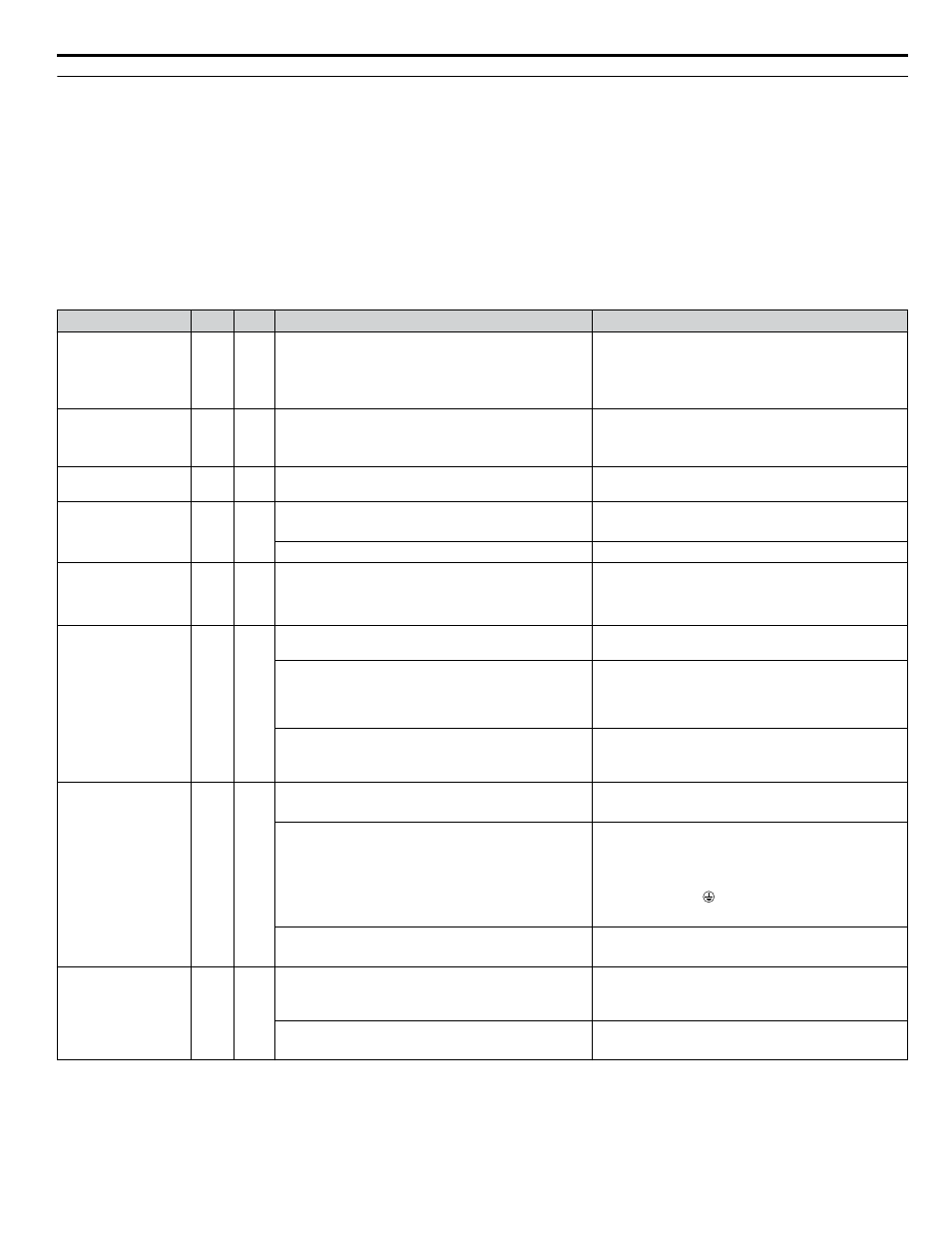
Digital Operator
ALM FLT
Cause
Possible Solution
Baseblock
bb
O
External baseblock signal was entered via one of the
multi-function input terminals (S1 to S8).
Check external sequence and baseblock signal input
timing.
Note: Baseblock alarm “bb” will not activate a digital
output programmed for minor fault H2-0o = 10. Set
H2-0o = 8 or 1B to activate a digital output for “bb”.
Control Circuit Fault
CPF02 to CPF24
O
There is a problem in the drive control circuit.
• Cycle the drive power supply.
• Initialize the drive.
• Replace the drive if the fault occurs again.
Control Circuit Fault
CPF25
O
Terminal board is not connected correctly
Reconnect the terminal board to the connector on the
drive, then cycle the power to the drive.
Option External Fault
EF0
O
O
An external fault was received from the PLC and F6-03
is set to a value other than 3.
• Remove the cause of the external fault.
• Remove the external fault input from the PLC.
Problem with the PLC program
Check the PLC program and correct problems.
Forward/Reverse Run
Command Input Error
EF
O
Sequence error
Check the forward and reverse command sequence and
correct the problem.
Note: When minor fault EF detected, motor ramps to
stop.
External Faults
EF1 to EF8
O
O
An external fault was triggered by an external device via
one of the digital inputs S1 to S8.
Remove the cause of the external fault and reset the fault.
Wiring is incorrect.
• Ensure the signal lines have been connected properly
to the terminals assigned for external fault detection
(H1-oo = 2C to 2F).
• Reconnect the signal line.
Multi-function contact inputs are set incorrectly.
• Check if the unused terminals have been set for
H1-oo = 2C to 2F (External Fault).
• Change the terminal settings.
Ground Fault
GF
O
Motor insulation is damaged
• Check the insulation resistance of the motor.
• Replace the motor.
A damaged motor cable is creating a short circuit
• Check the motor cable.
• Remove the short circuit and reapply power to the
drive
• Check the resistance between the cable and the
ground terminal .
• Replace the cable.
Excessive leakage current at the drive output
• Reduce the carrier frequency.
• Reduce the amount of stray capacitance.
Output Phase Loss
LF
O
The output cable is disconnected
• Check for wiring errors and properly connect the
output cable.
• Correct the wiring.
The motor winding is damaged
• Check the resistance between motor lines.
• Replace the motor if the winding is damaged.
i.7 Troubleshooting
YASKAWA ELECTRIC TOEP YAIP1U 03B YASKAWA AC Drive – P1000 Safety Precautions
55