6 parameter correspondence table, Appendix, V74x – Yaskawa VS606 V74X V7 to V1000 User Manual
Page 15
PL.V1000-4X.01 Transition Guide 6/22/10
Page 15 of 32
Yaskawa America, Inc.
Product Transition Guide
PL. V1000-4X.01 Rev: 6/22/10
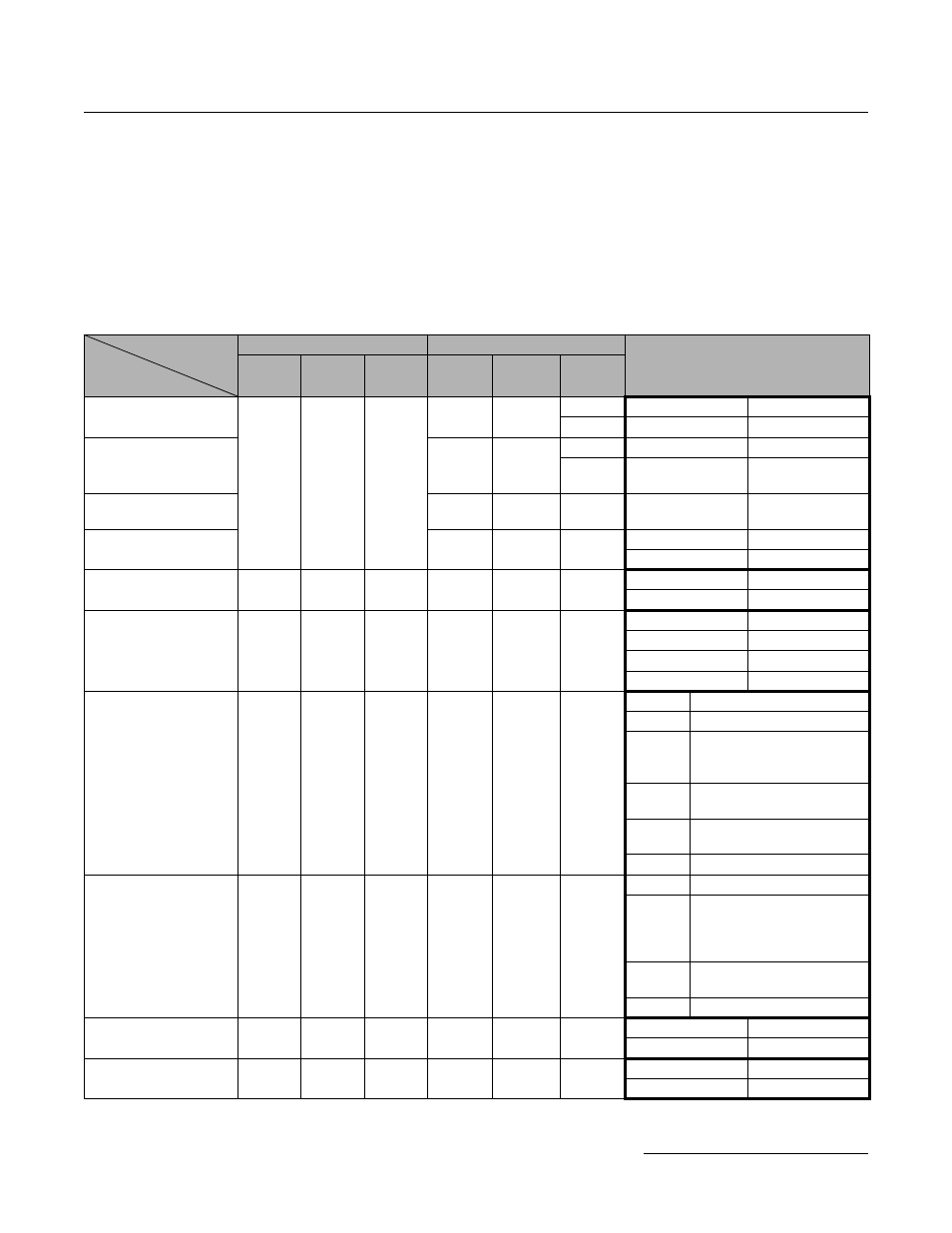
1.6 Parameter Correspondence Table
V74X and V1000-4X Differences in Parameter Settings
The list in Section 1.6 shows the parameter relations between the V74X and the V1000-4X. It lists the parameters and setting
values necessary for V74X replacement by a V1000-4X, but does not show the complete V1000-4X parameters and extended
parameter setting ranges. For details about new functions, parameters and parameter settings refer to the instruction manual
V74X V1000-4X Parameter Correspondence for Drive Replacement
Drive
Parameter
Function
V74X
V1000-4X
Note
Param.
No.
Initial
Value
Set
Value
Param.
No.
Initial
Value
Set
Value
Parameter access level
n001
1
A1-01
2
V74X
V1000-4X
n001 0
A1-01 0
Initialization
A1-03
0
n001 1~4
A1-01 2
n001 5
A1-01 2
b1-08 1
RUN cmd. In PRG mode
sel.
b1-08
0
n001 6
o4-11 1
Initialize mode (Spec.)
o2-09
0
n001 10
A1-03 2220
n001 11
A1-03 3330
Control mode selection
n002
0
A1-02
0
n002 0
A1-02 0
n002 1
A1-02 2
RUN command source
selection
n003
0
b1-02
1
n003 0
b1-02 0
n003 1
b1-02 1
n003 2
b1-02 2
n003 3
b1-02 3
Frequency reference
source selection
n004
0
b1-01
1
n004 0
— (no operator pot)
n004 1
b1-01 0
n004 2
b1-01 1 and
(H3-01 0 (term. A1) or
H3-09 0 (term. A2))
n004 3
b1-01 1 and H3-09 2
(term. A2)
n004 4
b1-01 1 and H3-09 3
(term. A2)
n004 5
b1-01 4
Frequency reference by
analog input A2 (signal
level) selection
n004
n078
0
1
H3-09
2
n004 6
b1-01 2
n004 7
n078 0
b1-01 1 and
(H3-01 0 (term. A1)
or
H3-09 0 (term. A2))
n004 8
n078 1
b1-01 1 and H3-09 2
(term. A2)
n004 9
b1-01 3
Stop method selection
n005
0
b1-03
0
n005 0
b1-03 0
n005 1
b1-03 1
Reverse operation
selection
n006
0
b1-04
0
n006 0
b1-04 0
n006 1
b1-04 1