Yaskawa J7 to J1000 User Manual
Page 7
(Header Title) Application Note
Doc#: PL.J1000.01 Copyright Yaskawa Electric America, Inc.©2008 www.yaskawa.com August 1, 2008 7 of 19
Subject: Transition Guide
Product: J1000
Document: PL.J1000.01
Title: Product Transition Guide – J7 to J1000
Product Transition Guide – J7 to J1000
4.3 DIP Switches
Note: When replacing a J7 drive with a J1000 drive, verify that DIP Switches (S1 and S3) are set properly.
J7
J1000
Function
Switch
Default
Switch
Default
NPN / PNP Selection
SW7 NPN S3
SINK
(NPN)
Analog input 1 level selection
SW8 Voltage S1 Voltage
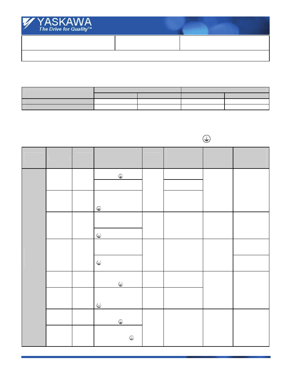
4.4 Main Terminal Size / Electric Wire Differences
Note: The J7 drive has main terminals at the top and bottom, while the J1000 drive has all main terminals at the bottom. Ensure
that all wires fit without tension
.
=
Ground
Terminal
Voltage
Class
Drive
CIMR-
JU
Terminal Symbol
Screw
Size
Tightening
Torque
N.m
(lb - in.)
Wire Size
mm
2
(AWG)
Recommended
Wire Size
mm
2
(AWG)
R / L1, S / L2, T / L3,
—, +1, +2,
0.8 ~ 1.0
(7.1 to 8.9)
J7
20P1
20P2
20P4
20P7
U / T1, V / T2, W / T3
1.24
(11.0)
J1000
2A0001
2A0002
2A0004
2A0006
R / L1, S / L 2, T / L3,
U / T1, V / T2, W / T3,
—, +1, +2, B1, B2,
(2 terminals)
M3.5
0.8 ~ 1.0
(7.1 to 8.9)
0.75 ~ 2.0
(18 to 14)
2
(14)
R / L1, S / L 2, T / L3,
U / T1, V / T2, W / T3,
—, +1, +2
J7
21P5
M3.5
0.8 ~ 1.0
(7.1 to 8.9)
2.0 ~ 5.5
(14 to 10)
2
(14)
R / L1, S / L 2, T / L3,
U / T1, V / T2, W / T3,
—, +1, +2, B1, B2
2
(14)
J1000
2A0010
(2 terminals)
M4
1.2 ~ 1.5
(10.6 to 13.3)
2.0 ~ 5.5
(14 to 10)
3.5
(12)
J7
22P2
R / L1, S / L 2, T / L3,
U / T1, V / T2, W / T3,
—, +1, +2,
M3.5
0.8 ~ 1.0
(7.1 to 8.9)
J1000
2A0012
R / L1, S / L 2, T / L3,
U / T1, V / T2, W / T3,
—, +1, +2, B1, B2,
(2 terminals)
M4
1.2 ~ 1.5
(10.6 to 13.3)
2.0 ~ 5.5
(14 to 10)
3.5
(12)
J7
23P7
R / L1, S / L 2, T / L3,
U / T1, V / T2, W / T3,
—, +1, +2,
Three –
Phase
200 V
J1000
2A0020
R / L1, S / L 2, T / l3, U
/ T1, V / T2, W / T3, —,
+1, +2, B1, B2, (2
terminals)
M4
1.2 ~ 1.5
(10.6 to 13.3)
2.0 ~ 5.5
(14 to 10)
5.5
(10)