Yaskawa J7 to J1000 User Manual
Page 11
(Header Title) Application Note
Doc#: PL.J1000.01 Copyright Yaskawa Electric America, Inc.©2008 www.yaskawa.com August 1, 2008 11 of 19
Subject: Transition Guide
Product: J1000
Document: PL.J1000.01
Title: Product Transition Guide – J7 to J1000
Product Transition Guide – J7 to J1000
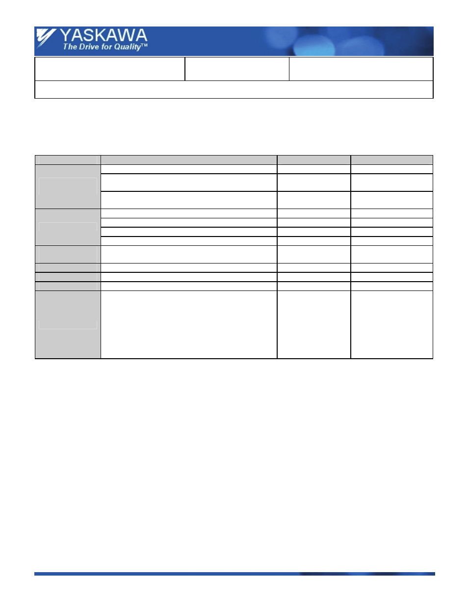
6.0 Option Replacements
The table below indicates potential option replacements.
Note: J7 options are not compatible with the J1000 drive.
Type
Description
J7
J1000
Interface for Remote Operator
SI-232 / J7
SI-232 / J
Interface for RS-232 PC communication
(MEMOBUS / Modbus)
SI-232 / J7C
SI-232 / JC
Serial
Communications
Interface for RS-422 / 485 communication
(MEMOBUS / Modbus)
SI-485 / J7
SI-485 / J
Remote operator without potentiometer JVOP-146
JVOP-182
Remote operator with potentiometer JVOP-144
Not
Available
Extension Cable 1 meter
UWR0051
UWR0051
Operator Panel
Extension Cable 3 meter
UWR0052
UWR0052
Potentiometer
Option
To use a potentiometer on the drive for settings up the
frequency reference.
Built-in
AI-V3 / J
DIN Rail Mounting
Used to mount the drive on a DIN Rail.
EZZ08122x
EZZ08122x
AC Reactor
3% or 5% AC Line Reactor
05P00620-xxxx
05P00620-xxxx
DC Link Choke
3% DC Link Choke
05P00620-xxxx
05P00620-xxxx
Copy Unit
Copy unit or keypads used to upload / download drive
parameters from one drive to another.
JV0P-140 or
JV0P-142
and
• SI-232 / J7 or / J7C
and
• UWR0051 (1 m )
or
• UWR0052 (3 m)
JV0P-182
(LED operator)
or JV0P-181
(USB Copy Unit)
and
• SI-232 / J or / J7C
and
• Same cables as J7