Yaskawa J7 to J1000 User Manual
Page 12
(Header Title) Application Note
Doc#: PL.J1000.01 Copyright Yaskawa Electric America, Inc.©2008 www.yaskawa.com August 1, 2008 12 of 19
Subject: Transition Guide
Product: J1000
Document: PL.J1000.01
Title: Product Transition Guide – J7 to J1000
Product Transition Guide – J7 to J1000
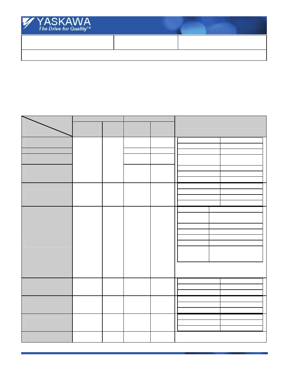
7.0 Parameter Settings
7.1 Parameter Correspondence for Drive Replacement
Note:
1. Before setting up other parameters, verify that C6-01 is set to “0” (HD). Refer to the Technical Manual for details on the
Normal and Heavy Duty selection.
2. Voltage values are valid for a 200 V drive. Voltage values double for the 400 V drive.
J7
J1000
Drive
Function
/ Parameter
Parameter
No.
Initial
Value
Parameter
No.
Initial
Value
Comments
Parameter Access
Level
A1-01 2
Initialization
A1-03 0
RUN command in
Programming Mode
b1-08 0
Fault History U2
Initialization
n01 1
o4-11 0
J7 J1000
n01 Æ 0
A1-01 Æ 0
n01 Æ 1
A1-01 Æ 2
n01 Æ 5
A1-01 Æ 2
b1-08 Æ 1
n01 Æ 6
o4-11 Æ 1
n01 Æ 10
A1-03 Æ 2220
n01 Æ 11
A1-03 Æ 3330
RUN Command Source
Selection
n02 1
b1-02 1
J7 J1000
n02 Æ 0
b1-02 Æ 0
n02 Æ 1
b1-02 Æ 1
n02 Æ 2
b1-02 Æ 2
Frequency Reference
Source Selection
n03 2
b1-01 1
J7 J1000
n03 Æ 0
b1-01 Æ 0 (A1-V3 / J
option required)
n03 Æ 1
b1-01 Æ 0
n03 Æ 2
b1-01 Æ 1 & H3-01 Æ 0
n03 Æ 3
b1-01 Æ 1 & H3-01 Æ 2
n03 Æ4 b1-01
Æ
1 & H3-01 Æ 3
n03 Æ 6
b1-01 Æ 2
(SI – 485 / J option
required)
When using A1 as frequency reference input,
make sure to set DIP switch S1 properly
(voltage or current input).
Stop Method Selection
n04 0
b1-03 0
J7 J1000
n04 Æ 0
b1-03 Æ 0
n04 Æ 1
b1-03 Æ 1
Reverse Run Prohibit
Selection
n05 0
b1-04 0
J7 J1000
n05 Æ 0
b1-04 Æ 0
n05 Æ 1
b1-04 Æ 1
Digital Operator STOP
Key Function
n06 0
o2-02
1
J7 J1000
n06 Æ 0
o2-02 Æ 1
n06 Æ 1
o2-02 Æ 0
Frequency Reference in
Local Mode
n07
0
—
—
(No operator panel potentiometer)