Yaskawa J7 to J1000 User Manual
Page 18
(Header Title) Application Note
Doc#: PL.J1000.01 Copyright Yaskawa Electric America, Inc.©2008 www.yaskawa.com August 1, 2008 18 of 19
Subject: Transition Guide
Product: J1000
Document: PL.J1000.01
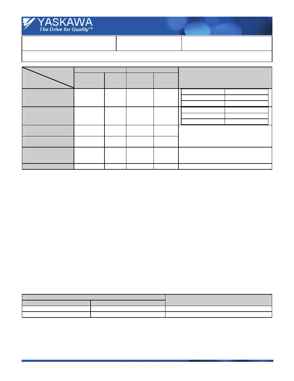
Title: Product Transition Guide – J7 to J1000
Product Transition Guide – J7 to J1000
J7
J1000
Drive
Function
/ Parameter
Parameter
No.
Initial
Value
Parameter
No.
Initial
Value
Comments
RTS Flow Control
On / Off
n74 0
H5-07 1
J7 J1000
n74 Æ 0
H5-07 Æ 1
n74 Æ 1
H5-07 Æ 0
Low Speed Carrier
Frequency Reduction
n75 0
L8-38
Depends
on drive
capacity
J7 J1000
n75 Æ 0
L8-38 Æ 0
n75 Æ 1
L8-38 Æ 1
COPY Function
Selection
n76 Ready
o3-01 0
READ Prohibit
Selection
n77 0
o3-02 0
Possible with copy unit or remote operator.
Fault History
n78
—
U2-01 / 02
—
In the J1000, the last current fault and the last
fault can be seen in parameter U2-01 and
U2-02.
Software Version
n79
—
U1-25 / 26
—
—
7.2 Parameter Differences
•
Maximum Carrier Frequency -
— J7:
n46, maximum 10 kHz.
— J1000:
C6-02, maximum 15 kHz.
•
S-Curve Setting -
— J7:
Fixed settings.
— J1000:
Set in seconds.
•
Stall Prevention Level -
The stall prevention level during acceleration and constant speed run depends on the duty mode setting.
— J7:
The maximum setting of n56 / 57 is 200%.
— J1000:
Heavy Duty, The maximum setting of L3-02 and L3-06 is 150%.
Normal Duty, The maximum setting of L3-02 and L3-06 is 120%.
7.3 Special Software Replacement
The table below indicates replacement information for J7 drives with standard or special software.
Note:
Software ID numbers are printed on the nameplate.
J7
Software Number
Description
J1000
001x, 002x
J7 Standard Drive Software
Covered by standard software functionality.
Others
—
Contact your Yaskawa sales representative.