Electronic lineshaft with alignment, 0 i/o definitions, 1 new multi-function digital input settings – Yaskawa G5 Electronic Lineshaft Alignment User Manual
Page 8: 2 new multi-function digital output settings, 1 changed factory defaults of standard parameters
Electronic Lineshaft with Alignment
Date: 07-01-04, Rev: 04-07
Page 8 of 15
TM.G5SW.046
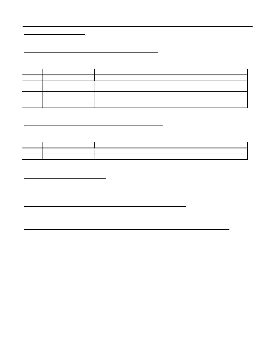
2.0 I/O Definitions
2.1 New Multi-Function Digital Input Settings
For constants H1-01 through H1-06.
Setting Display
Description
80
Disable LineShft
Closed: Line Shaft Mode is disabled
83
Advance Slave
Closed: Slave drive will increase speed without accumulating error
84
Retard Slave
Closed: Slave drive will decrease speed without accumulating error
85
Slave Trigger
Closed: The slave encoder has achieved the alignment position
86
Master Trigger
Closed: The master encoder has achieved the alignment position
87
Align Slave
Closed: The error count between the triggers will be corrected
2.2 New Multi-Function Digital Output Settings
For constants H2-01 through H2-03.
Setting Display
Description
40
Alignment Check
On = The alignment has check was within the set range
42
Aligned
On = The alignment function was performed successfully
3.0 Configuration Notes
This software document is only a supplement to the GPD515/G5 Series instruction manual. All parameters and
features not mentioned in this document have not changed.
3.1 Changed Factory Defaults of Standard Parameters
None
3.2 Minimum Programming Requirements for “Line Shaft” Operation
1. The follower VFD must be programmed for the Flux Vector control method, A1-02 = 3.
2. The follower’s run and reference sources, B1-01 and B1-02, must be set to 5:Line Shaft.