Electronic lineshaft with alignment, 1 sample application – Yaskawa G5 Electronic Lineshaft Alignment User Manual
Page 3
Electronic Lineshaft with Alignment
Date: 07-01-04, Rev: 04-07
Page 3 of 15
TM.G5SW.046
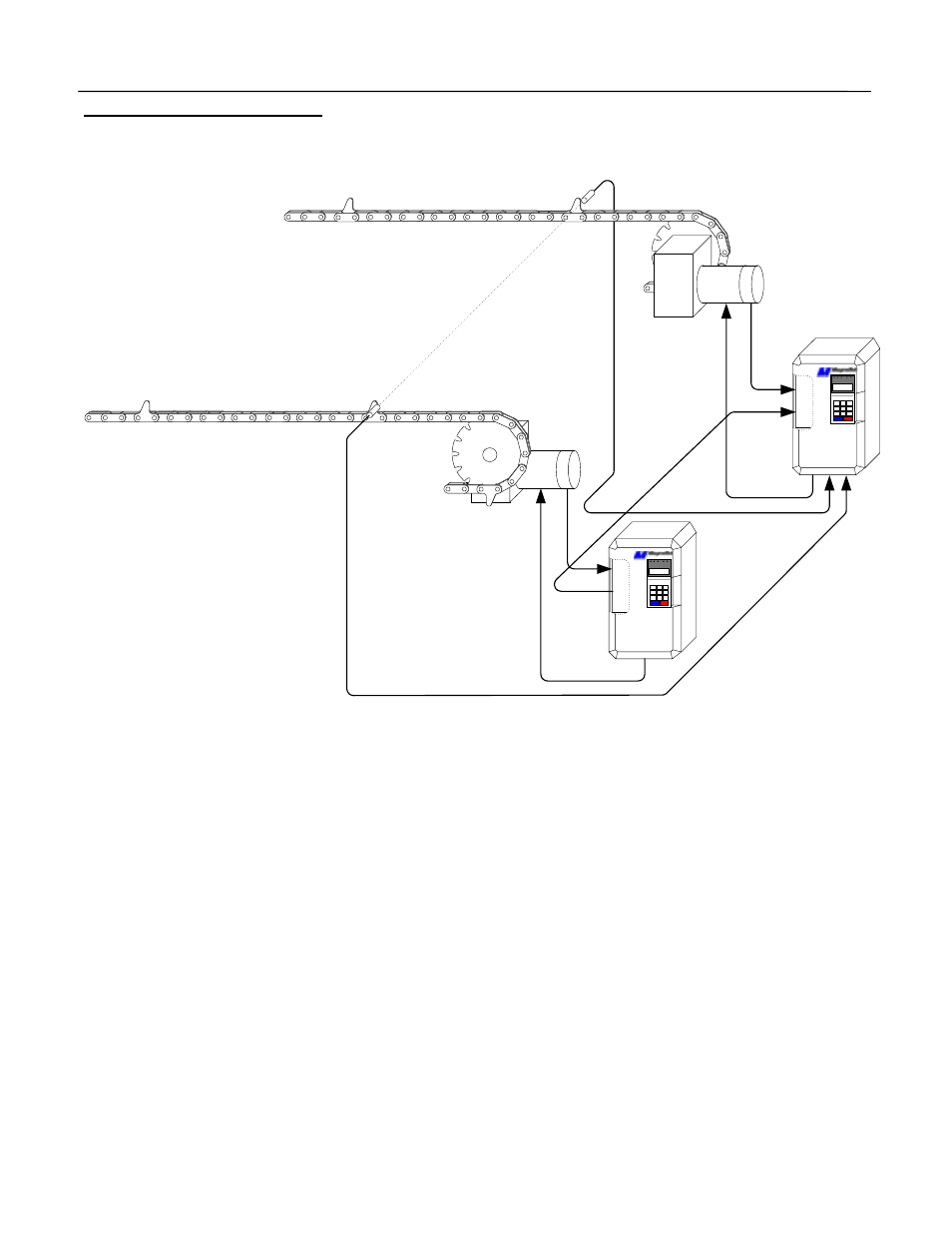
1.1 Sample Application
This example shows two pusher chains. Each chain is mechanically isolated from the other. The master
and slave trigger switches are placed in line providing an alignment position for the pushers. The pusher’s
leading edge will activate the switches as they pass.
When this line starts alignment is necessary. The “Align Slave” input must be activated and maintained to
cause the alignment feature to operate. The slave drive will align itself after the trailing pusher has
triggered. The “Aligned” output indicates that the alignment procedure was successful and that the “Align
Slave” input may be removed. If this input is not removed alignment will occur each time a pusher passes a
trigger switch. The pushers will be aligned to the associated trigger switch position.
The lineshaft software will maintain the follower’s position in respect to the master. The follower position is
monitored and if it exceeds the users set value a following fault or alarm will result. The alignment check
will also monitor the quadrature counts between the triggers. An “Alignment Check” output will remain on if
the check was within the set range.
PG-W2
GPD
515
PG-X2
GPD
515
Ma
ste
r Trig
g
e
r S
witch
Sl
ave Tr
ig
ger
Sw
it
ch
Ma
st
e
r Mo
to
r
Sl
ave M
o
tor
M
a
ster
Encoder
Sl
ave Encoder
Gear
Box
Slave
Motor
Master
Motor
A
lig
ne
d