F7 drive with els, Pg -w2 o pt ion card – Yaskawa E7 Drive Technical Manual User Manual
Page 24
Date: 02/25/2010, Rev: 10-02
Page 24 of 34
TM.F7SW.064
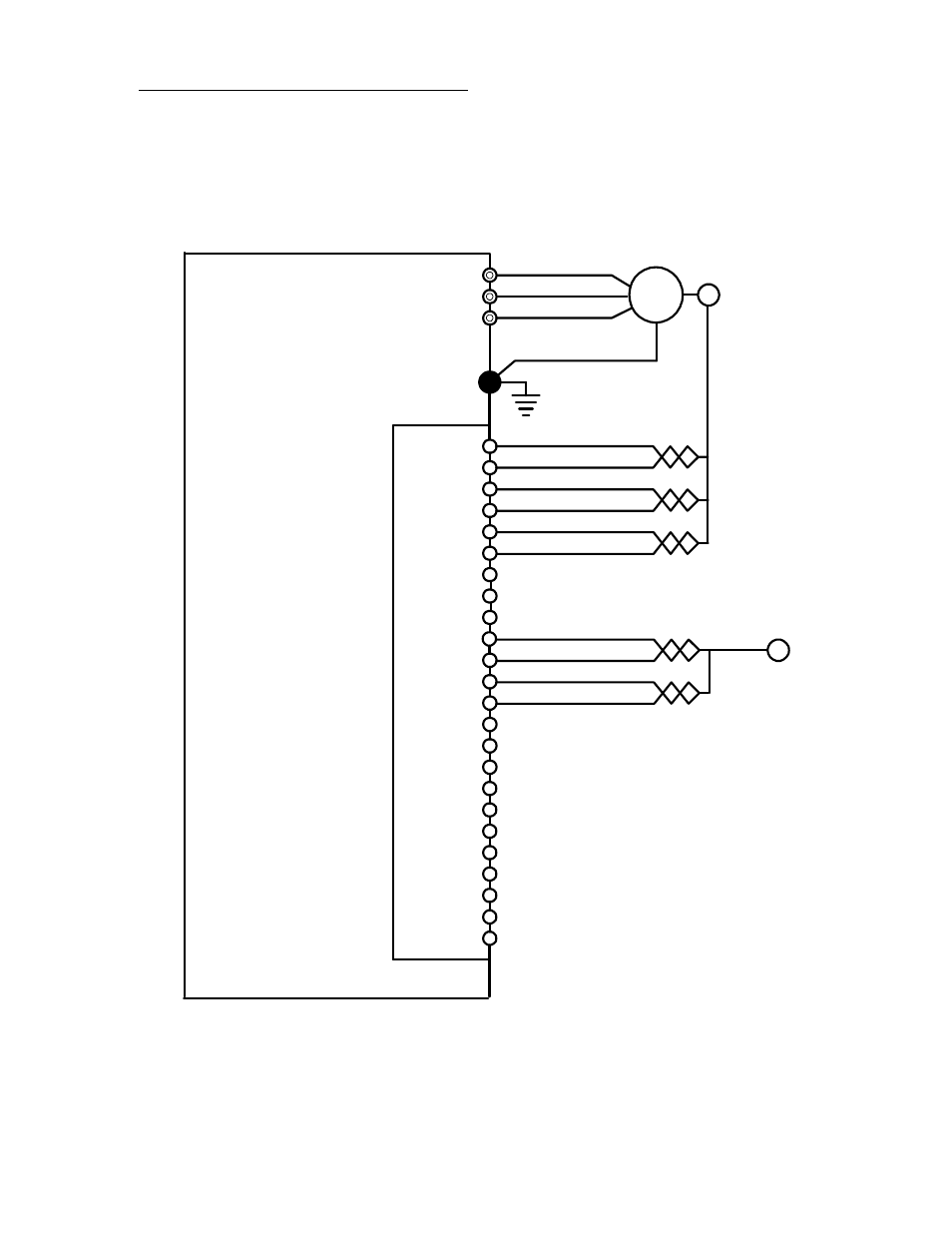
5.3 Wiring the Encoders for Electronic Lineshaft
The master signal (encoder) and the follower encoder must be wired to a dual input encoder card (ex.
PG-W2). All signals need to be a line driver type circuit. Wire the master signal (encoder) input into
terminals 10 ~ 13 of the PG-W2. Wire the follower encoder input into terminals 3 ~ 6 of the PG-W2. For
other dual input encoder cards, consult their installation guide for exact terminals. The marker (Z) pulse is
not required for this Electronic Lineshaft software. The figure below details the wiring of the PG-W2 option
card.
IM
12VDC Supply
Common
A+
A-
B+
B-
1
2
3
4
5
6
7
8
9
GND
P
G
-W2 O
pt
ion
Card
T1
T2
T3
Motor
11
12
13
14
15
16
A+
A-
B+
B-
10
17
18
19
20
21
22
23
24
Follower
Encoder
Master
Encoder
Note: The master encoder may be
powered by the PG-W2 if the combined
current draw of both encoders does not
exceed the 200mA power supply rating of
the PG-W2. If the combined current draw
is more than 200mA, power the master
encoder using an external power supply.
F7 Drive
with ELS
Wiring Example of PG-W2 Option Card