Yaskawa E7 Drive Technical Manual User Manual
Page 14
Date: 02/25/2010, Rev: 10-02
Page 14 of 34
TM.F7SW.064
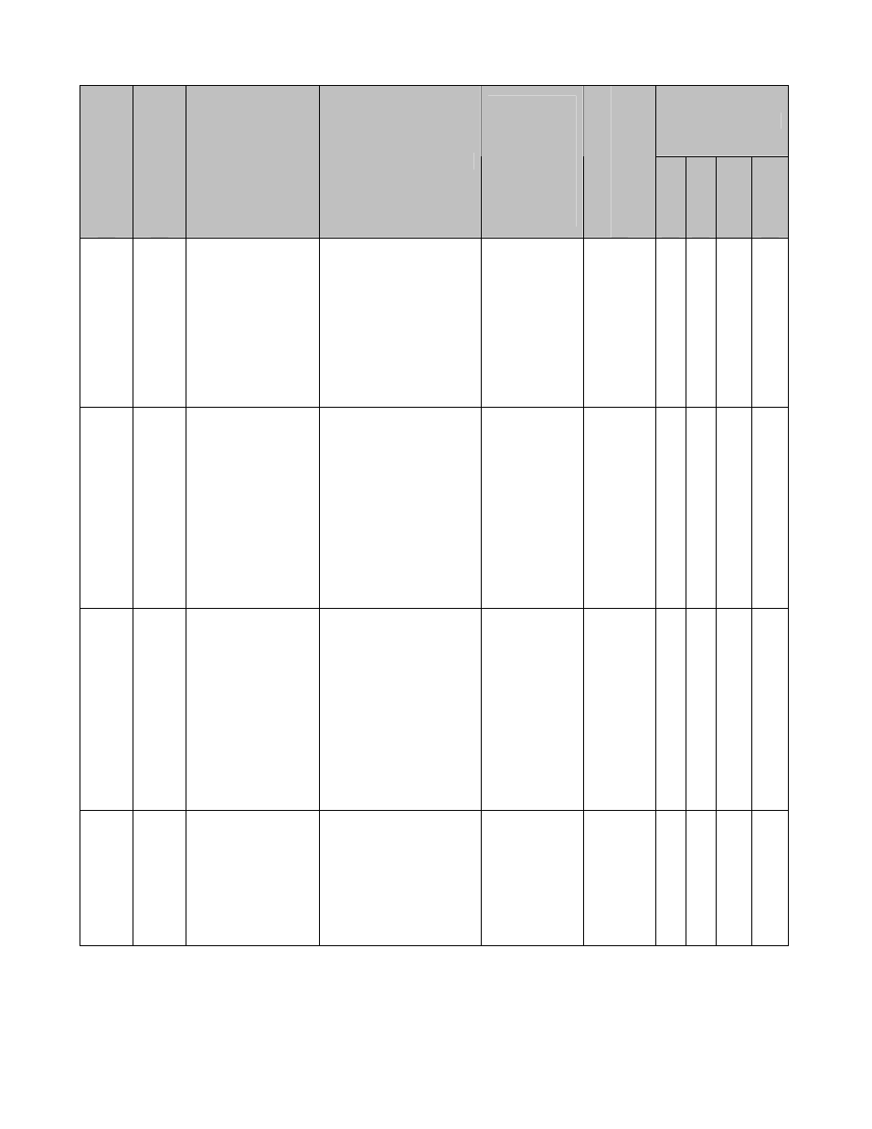
4.2 Monitors (U1-XX) (continued)
Control Mode *1
Monitor Num
ber
Modbu
s A
dd
re
ss
Monitor Name
Digital Operator
Display
Description
Scaling for
Multi-function
Analog
Output
Terminals
FM and AM
(H4-01, H4-
04)
Unit
V/f
V/f w/
PG
Open
Loop
Vector
Flux Vector
U1-93 723H
Follower
Reference After
Gear Ratio
Adjustment
Fref After Adj
Displays the frequency
from the master
encoder after the
digital, analog, MOP
and network
communication gear
ratio adjustments are
applied.
100% =
Maximum
Output
Frequency
(E1-04)
0.1
Hz
Q Q Q Q
U1-94 724H
Master
Counts/5ms
Master Cts/5ms
Displays the number of
quadrature encoder
counts per 5ms scan
from the master drive.
Note: ELS modes only.
Note: This monitor is
representative only
and should be used
only to confirm that
encoder counts are
being received.
100% =
Counts/5ms
at Maximum
Output
Frequency
(E1-04)
Counts Q Q Q Q
U1-95 725H
Follower
Counts/5ms
Follower Cts/5ms
Displays the number of
quadrature encoder
counts per 5ms scan
from the follower drive.
Note: ELS modes only.
Note: This monitor is
representative only
and should be used
only to confirm that
encoder counts are
being received.
100% =
Counts/5ms
at Maximum
Output
Frequency
(E1-04)
Counts Q Q Q Q
U1-96 726H
Position Error
Position Error
Displays the position
error between the
master and follower
encoders in quadrature
follower encoder
counts.
Note: ELS modes only.
100% =
Maximum
Output
Frequency
(E1-04)
1
Count
*2
Q Q Q Q
*1: Access Level (A1-01): Q = “Quick Start”, A = “Advanced”, F = “Factory”.
*2: Unit is dependent on the setting of the Position Units Selection (P1-10). When the position error is greater
than the maximum value that can be displayed, the digital operator will flash “OVER” in place of the U1-96 data.
When reading by network communication (register 726H), the unit is fixed at quadrature encoder counts.