4 option components, Si-ep3 option, Communication modular connector cn1 port 1/port 2 – Yaskawa SI-EP3 PROFINET Technical Manual User Manual
Page 9: 4option components, A1000
4 Option Components
YASKAWA ELECTRIC
SIEP C730600 69A 1000-Series Option SI-EP3 Technical Manual
9
4
Option Components
SI-EP3 Option
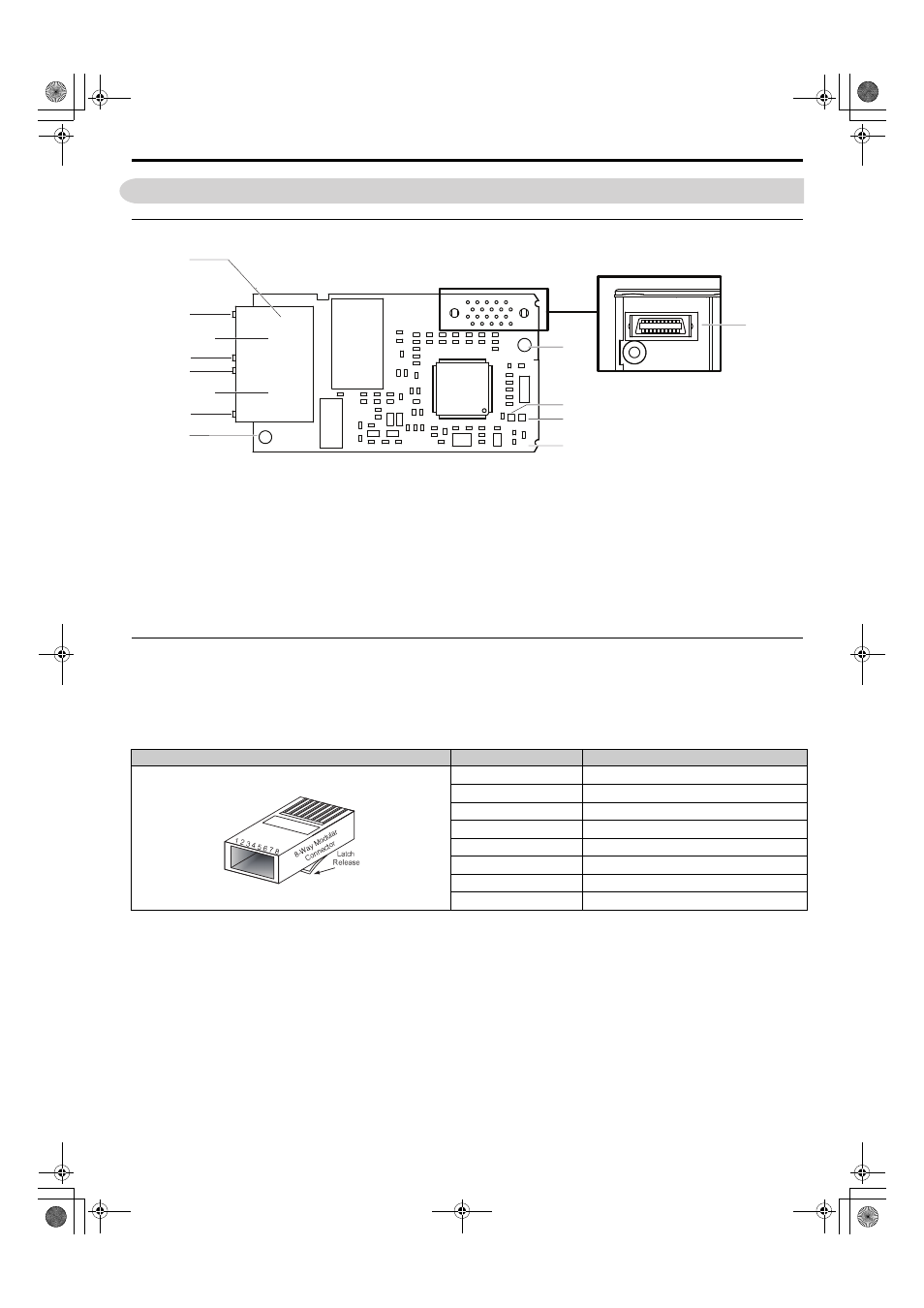
Figure 1
Figure 1 PROFINET Option Components
Communication Modular Connector CN1 Port 1/Port 2
The communication modular connector CN1 on the option is a modular dual RJ45 female connector designated port 1
and port 2. Port 1 and port 2 are the connection point for a customer supplied male Ethernet network communication
cable.
Table 3 Male 8-way Ethernet Modular Connector (Customer-Supplied)
A – Option connector
H – Port 1
B – Installation hole
I – Port 1 LED (LINK/ACT)
Refer to Option LED Display on page 10
for details on the LEDs.
<2> The ground wire provided in the option shipping package must be connected during installation.
C – LED (NS)
J – Port 2 LED (10/100)
D – LED (MS)
K – Port 2
E – PROFINET PCB
L – Port 2 LED (LINK/ACT)
F – Ground terminal and installation hole
M – PROFINET cable connection
G – Port 1 LED (10/100)
Male EtherNet 8-Way Modular Connector
Pin
Description
1 (Pair 2)
Transmit data (TXD) +
2 (Pair 2)
Transmit data (TXD) -
3 (Pair 3)
Receive data (RXD) +
4 (Pair 1)
Not used
<1> Not used for 10 Mbps and 100 Mbps networks.
5 (Pair 1)
6 (Pair 3)
Receive data (RXD) -
7 (Pair 4)
8 (Pair 4)
E
F
A
M
L
J
G
I
K
H
B
C
D
Underside
A1000
PROFINET_E_conditional.book 9 ページ 2015年2月25日 水曜日 午後5時17分